
Section V
TM 11-6625-2781-14&P-2
ADJUSTMENT PROCEDURES
5-22. First Local Oscillator Adjustment
REFERENCE: Service Sheets 5, 8.
DESCRIPTION:
After the display and IF sections are adjusted, the first local oscillator is adjusted on the 0-110 MHz range. Adjustments
are first made at the end points of the frequency dial and then the midpoints are adjusted in 10 MHz increments. The 0-
11 MHz range is selected and the frequency is adjusted at the 0 and 11 MHz points.
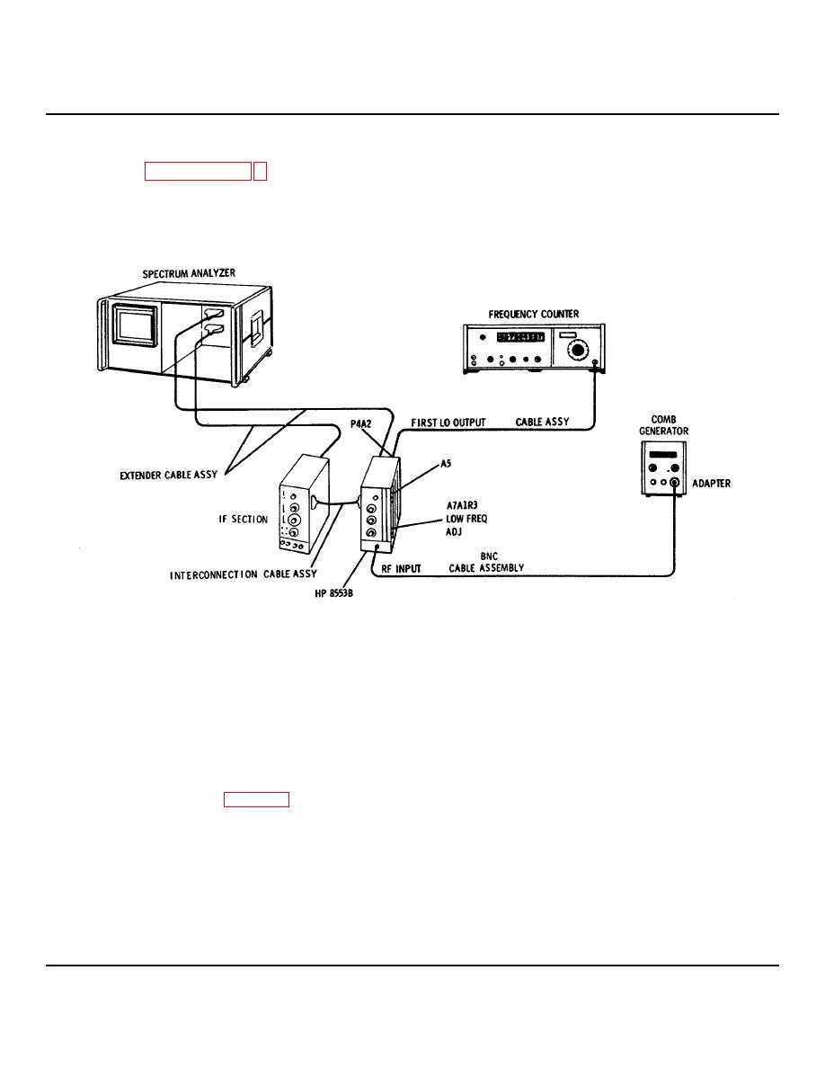
Figure 5-1. First Local Oscillator Adjustment Test Setup
EQUIPMENT:
Comb Generator ................................ ................................ ................................ ................................ ....... HP 8406A
Frequency Counter with 5252A Plug-in ................................ ................................ ................................ ...... HP 5245L
BNC Cable Assembly................................ ................................ ................................ .............................. HP 10503A
Type N male-to-BNC female Adapter ................................ ................................ ................................ ...... UG-201A/U
Extender Cable Assembly ................................ ................................ ................................ ............... HP 11592-60015
Interconnection Cable Assembly ................................ ................................ ................................ ..... HP 11592-60016
Cable Assembly ................................ ................................ ................................ .............................. HP 11592-60013
1. Connect the setup in Figure 5-1. Make the following control settings:
ANALYZER:
RANGE MHz ................................ ................................ ................................ ................................ ................... 0-110
FREQUENCY ................................ ................................ ................................ ................................ ................. 0 MHz
FINE TUNE................................ ................................ ................................ ................................ ................. Centered
BANDWIDTH ................................ ................................ ................................ ................................ ................. 30 kHz
SCAN WIDTH ................................ ................................ ................................ ................................ ....PER DIVISION
SCAN WIDTH PER DIVISION ................................ ................................ ................................ ........................ 1 MHz
INPUT ATTENUATION................................ ................................ ................................ ................................ .... 10 dB
5-5

