
TM 9-6625-1753-14
C2
(2) Set the DISPLAY LOGIC switch to TRIG-STROBE.
(3) Set the TIME DIV switch until several cycles of the signal appears on the screen.
(4) Pull out the DELAYED SWEEPPULL, TO UNLOCK switch and rotate it until the intensified segment is reduced to
a small bright dot.
(5) Rotate the DELAY VERNIER control until the bright spot is at the 50 percent point of the leading edge of the
desired pulse as shown in figure 2-4A.
(6) Record the DELAY VERNIE R control dial reading.
(7) Rotate the DELAY VERNIER control until the bright spot is at the 50 percent point of the trailing edge of the
desired pulse as shown in figure 2-4B.
(8) Record the DELAY VERNIER control dial reading.
(9) Subtract the dial rea ding obtained in step (6) from the dial reading obtained in step (8).
(10) Multiply the difference of the two dial readings by the setting of the TIME/DIV switch. The product is the pulse
width.
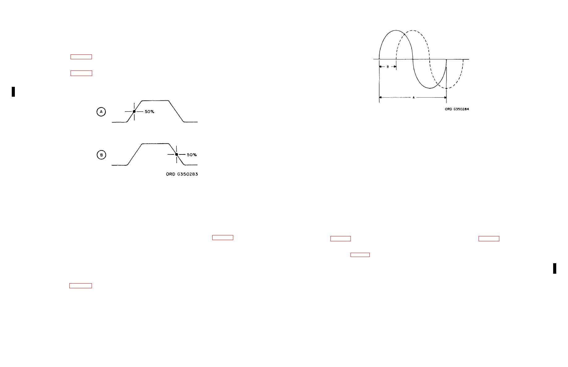
Figure 2-5. Phase shift measurements.
(8) Measure the horizontal distanc e between the start of one of the sine-wave signal to the start of the other (Fig. 2-
5). Call this distance B.
b. Calculate the phase shift as follows:
(1) Divide the distance (B) found by step a(8) by the distance (A) found in step a(7).
(2) Multiply the quotient thus obtained by 360 degrees. The resultant is the phase difference between the two
sinewave signals:
B
Phase-shift-difference = = - x 360
Figure 2-4. Pulse width measurements using the
A
DELAY VERNIER control
Section IV. CHECK PROCEDURES
2-13. Phase Shift Measurements
Caution: To prevent damage to the equipment, assure that the power is off before inserting plug-in units into, or
To determine the phase difference between two sine-wave signals proceed as follows:
removing these units from the main frame.
a. Measure the distance betwee n the two sine waves displayed on the CRT screen as described in steps (1) through (8)
below.
2-14. General
(1) Apply one of the sine-wave signals to the channel A input and the other to the channel B input of the dual trace
plug-in.
This section contains the organizational check procedures for checking the operation of the oscilloscope. Two tables are
(2) Set up the delaying sweep plug -in for externally triggered normal sweep operation (par. 2-10). Use the sine-wave
provided: the first, table 2-4, is to be performed before operation and monthly; the second, table 2-5, pertains to the dual trace
signal source that is applied to the channel A input as the external trigger source.
plug-in 79-02A only, and is to be performed when trouble is suspected (nonperiodic).
(3) Set the MODE switch to ALT.
(4) Adjust the TIME/DIV switch until a couple of cycles of the display appear on the screen.
2-15. Oscilloscope Check (Fig. 2-6)
(5) Adjust the POSITION controls on the dual trace plug-in until the positive portion of the sine wave above the
horizontal graticule center line is equal to the negative portion of the signal below the line.
This paragraph covers the step-by-step procedure required to check the operation of the oscilloscope. The steps within each
(6) Adjust the POSITION control on the delaying sweep plug-in until the positive slope of one of the signals starts at
table are to be performed in the sequence given. The procedure is presented in tabular form and is explained in the following
the first left side vertical graticule line.
sample table. Notice that each indentation for test contained in the table lines up with the appropriate table heading. Under
(7) Measure the horizontal distance of one cycle of the sine-wave signal that starts at the firs t left side vertical
the heading Operation are the instructions (e.g. Check Normal Sweep) as well as a listing of those operations that must be
graticule line as shown in figure 2-5. Call this distance A.
performed in order to obtain a normal indication. Under the heading Normal indication is given what that normal indication
shall be, and under Corrective procedure is described the corrective action that is to be taken to restore the oscilloscope to its
proper operating condition.
2-7

