
TM 11-6625-256-14/TO 33A1-13-170-1
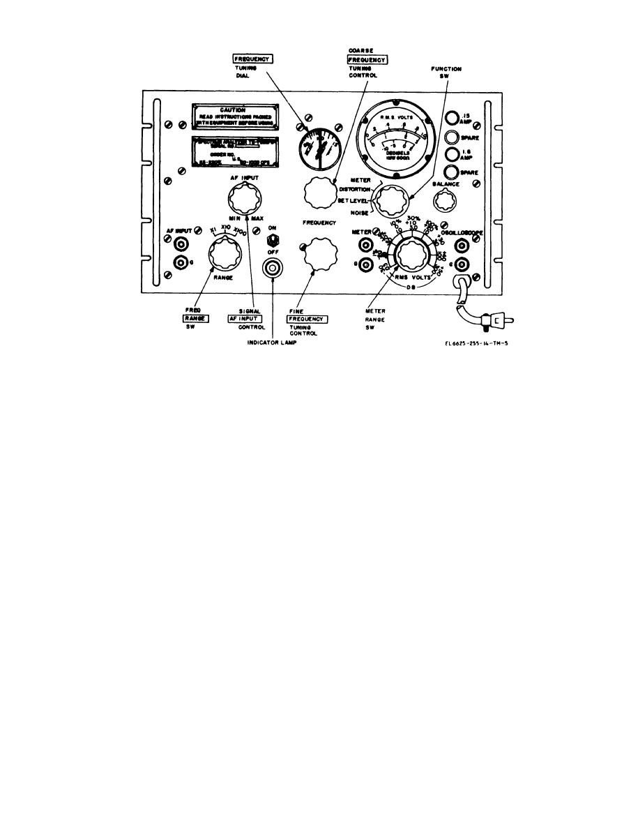
Figure 3-2. Front panel controls and indicators, Spectrum Analyzers TS-723B/U, TS-723C/U, and TS-723D/U.
Table 3-1. Operator Controls and Indicators
Function
Control, indicator, or fuse
Applies power to equipment.
ON/OFF power switch.
Glows when ON/OFF switch is ON,
ON/OFF indicator lamp (TS-723B/U, TS-723C/U, and
TS-723D/U).
Signal INPUT control.
Controls input level of applied signal in any position of func-
tion switch except METER position.
AF/RF selector switch (TS-723A/U only).
Selects input signal from either AF INPUT or AF-RF
INPUT binding posts. Leave switch in AF position.
Frequency RANGE switch.
Selects any of three frequency bands available. The frequency
range band is given below:
X l . . . . . . . . . . . . . . . . . . . . . 20 to 200 Hz.
X l 0 . . . . . . . . . . . . . . . . . . . . . 200 to 2,000 Hz.
Xl00 . . . . . . . . . . . . . . . . . . . . 2,000 Hz to 20 kHz.
FREQUENCY tuning dial.
Indicates reading of input signal frequency in conjunction
with frequency RANGE switch. Direct dial readings are
given from 20 to 200.
FREQUENCY tuning controls.
Tune spectrum analyzer to input signal frequency, within
limits set by frequency RANGE switch.
Coarse FREQUENCY control (upper knob),
Used for coarse tuning adjustments.
Used for fine tuning adjustments.
Fine FREQUENCY control (lower knob).
Selects desired function as follows:
Function switch.
Position
Function
Adjusts e q u i p m e n t t o
DISTORTION
measure harmonics of in-
put signal compared to a
reference level.
A d j u s t s input signal to a
SET LEVEL
reference level for distor-
t i o n measurements and
increases range level
when m e a s u r i n g noise
signals.
NOISE
Used for voltage measure-
ments of every weak sig-
nal inputs.
3-2
