
TM 11-6625-255-14/TO 33A1-13-170-1
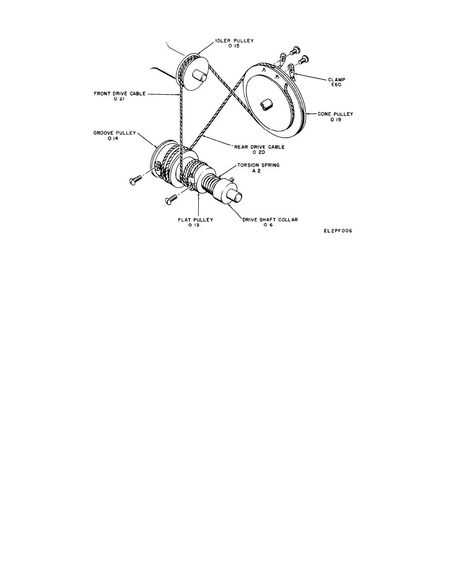
Figure 79. Replacing capacitor drive cables
act position of coupler 0 5 on the capacitor shaft.
screws that attach the capacitor drive assemble to the
Loosen the setscrew that attaches coupler 05 to the
front panel. Unsolder all wiring connections. Tag all
shaft of variable capacitor C13. Remove the No. 6-32
wires for identification during reassembly. Lift out
binder head screw that attaches each mounting
the capacitor drive assembly.
bracket A62. Slide variable capacitor C13 out of
(3) Remove the two 6-32 roundhead screws,
coupler 0 5 and remove it from the mounting chassis.
lockwashers, and nuts that attach dial window A8.
(7) Remove the two No. 6-32 screws, lock-
Remove dial window A8.
washers, and nuts that attach coupler 0 5 to the
(4) Slide shaft disk 02 off dial shaft 03. Turn
mounting bar of cone pulley 0 19. Slide coupler 0 5
frequency dial A5 fully clockwise, Carefully make a
from coupler shaft 08.
scribe line on the face of the mounting chassis direct-
ly in line with 200 on the dial scale. Remove the four
(8) If cables 0 20 and 0 21 are to be replaced,
cut the cables and remove the No. 4-40 screw that
screws that attach dial shaft 0 18, Remove dial shaft
attaches each cable to cone pulley 0 19, Loosen
0 18 and frequency dial A5. Slide out dial shaft 03.
the setscrew that attaches cone pulley 0 19 to
(5) Loosen the dial stop screw that attaches dial
coupler shaft 0 8. Slide cone pulley 0 19 and bear-
hub 0 9. Remove dial hub 0 9 and bearing washer 0 60.
ing washer 0 62 from coupler shaft 0.8. Loosen
Remove the No. 632 roundhead screw that attaches
the two setscrews that attach coupler shaft col-
back drive cable 020 to groove pulley 0 14. Remove
lar 0 4, Slide coupler shaft collar 0 4 and bearing
the No. 6-32 roundhead screw that attaches front
washer 0 61 from coupler shaft 0 8. Remove any
drive cable 0 21 to flat pulley 0 13. Loosen the two
burrs on coupler shaft 0 8 with No. 000 sand-
setscrews that attach dial shaft collar 0 6 and remove
paper before sliding the shaft out of the bearings.
torsion spring A2. Loosen the setscrew that attaches
groove pulley 0 14, flat pulley 0 13, and bearing
(9) Lift off idler pulley 0 15. Loosen the setscrew
washer 0 63 off drive shaft 0 22. Pull flat pulley 0 13
that attaches idler shaft 0 7, and lift out the shaft.
out of groove pulley 0 14. Carefully remove any burrs
(10) Remove the No. 6-32 screw that attaches
from the shaft with No. 000 sandpaper before pulling
cable clamps H60 and H61. Remove cable clamps H60
out drive shaft 0 22.
and H61. Loosen the No. 6-32 screw that attaches
lampholder XI 1 (XDS2). Remove the lampholder.
(6) Rotate variable capacitor C13 so that the
plates are completely meshed. Note and mark the ex-
(11) Loosen the setscrew that attaches disk
7-12
Change 1
