
Section V
TM 11-6625-2781-14&P-2
ADJUSTMENT PROCEDURES (cont'd)
5-22. First Local Oscillator Adjustment (cont'd)
ANALYZER Control Settings (cont'd)
BASE LINE CLIPPER ................................ ................................ ................................ ................................ ......... ccw
SCAN TIME PER DIVISION ................................ ................................ ................................ ........ 2 MILLISECONDS
LOG REF LEVEL ................................ ................................ ................................ ................................ ......... -10 dBm
LOG REF LEVEL Vernier................................ ................................ ................................ ................................ .... ccw
LOG-LINEAR ................................ ................................ ................................ ................................ ..................... LOG
VIDEO FILTER ................................ ................................ ................................ ................................ .................. OFF
SCAN MODE ................................ ................................ ................................ ................................ ....................... INT
SCAN TRIGGER ................................ ................................ ................................ ................................ ............ AUTO
8406A:
COMB FREQUENCY - MC ................................ ................................ ................................ ............................. 10 MC
INTERPOLATION AMPLITUDE................................ ................................ ................................ ......................... OFF
OUTPUT AMPLITUDE................................ ................................ ................................ ................................ .3 o'clock
5245L/5252A:
SAMPLE RATE................................ ................................ ................................ ................................ ............ 8 o'clock
SENSITIVITY................................ ................................ ................................ ................................ .............. PLUG IN
TIME BASE ................................ ................................ ................................ ................................ ..................... 10 ms
FUNCTION ................................ ................................ ................................ ................................ ......... FREQUENCY
MAX COUNT RATE................................ ................................ ................................ ................................ .... 350 MHz
2. Center dial pointer on 0 MHz using FREQUENCY control.
3. Select ZERO SCAN WIDTH, and center TUNING RANGE Adjust A5A1R13.
4. Adjust A7A1R3 LOW FREQ ADJ in the 8553B for maximum base line lift. (In ZERO SCAN WIDTH base line lift
is an indication that signals are present.)
5. Turn FREQUENCY to 110 MHz. The counter should read 310 MHz 10 MHz.
300
320 MHz
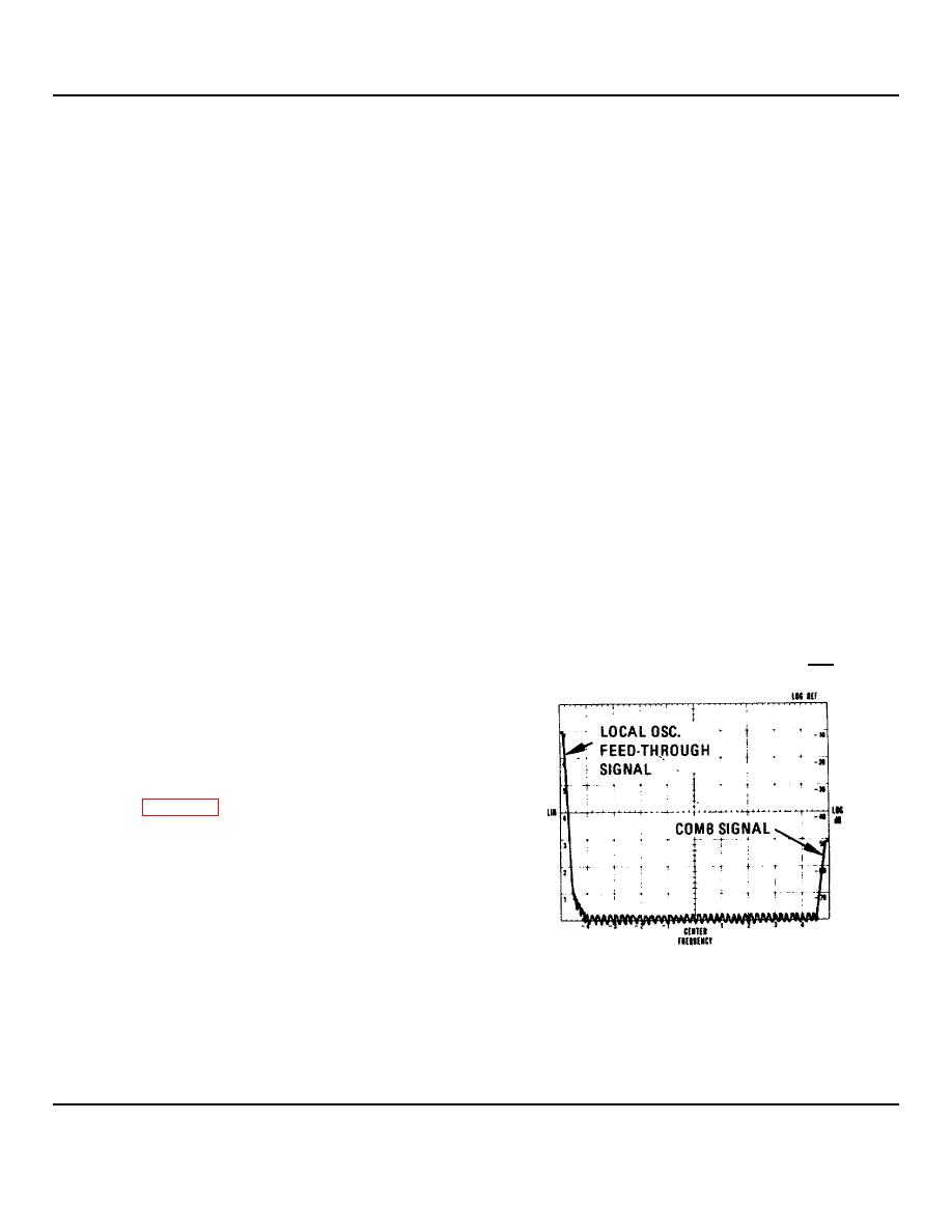
6. Turn SCAN WIDTH to PER DIVISION. Turn
FREQUENCY to 5 MHz. The local oscillator
feedthrough signal should appear on the left
edge of the graticule.
7. Tune FREQUENCY until half the feedthrough
signal appears at the left edge of the graticule.
See Figure 5-2.
8. Adjust A5A1R32 until half the comb signal
appears at the right edge of the graticule.
Readjust FINE TUNE and A5A1R32 as
necessary until half of each signal appears on
the edges of the graticule.
9. Select ZERO SCAN WIDTH. Measure the first
local oscillator frequency. The frequency should
be 205 0.5 MHz.
Figure 5-2. First Local Oscillator Adjustment: CRT
Display
11. The comb spectrum should be evenly distributed across the graticule. The center comb should be on the center
graticule 0.3 divisions (300 kHz).
12. Return the comb generator to the 10-MC comb.
5-6
