
Section VIII
Figure 8-39. Preset Scan A4 (08553-6008)
Figure 8-40. Frequency Range Assembly A13
Connectors, Test Point Voltages and
(08553-60123) Adjustments
Components Locations.
and Components Locations.
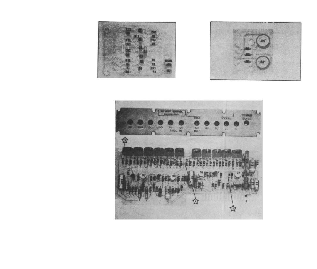
Figure 8-41. Voltage Control A5 (08553-6007) Adjustments, Test Points and Component Locations.
