
TM 11-6625-2781-14&P-2
SERVICE SHEET 7
TEST PROCEDURE
It is assumed that proper operating voltages are present
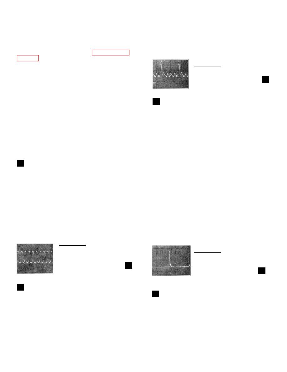
Connect the HP 180A/1801A/1821A to TP 2 (Q5-b) and
and that correct results could not be obtained in
observe the waveform.
performing the tests specified in Paragraph 5-27 of
CONTROL SETTINGS:
0.1 /sec/Div
TROUBLESHOOTING PROCEDURE
0.5 V/Div
3
When trouble has been isolated to the Reference
10:1 probes
Assembly it should be removed from the unit and
Waveform GOOD: proceed to
reinstalled on the extender board to provide easy access
Waveform BAD: Check Q6/Q7 and
to components. Troubleshooting information follows the
associated components
3
technical discussions of individual circuits.
DIVIDE-BY-FIVE CIRCUIT
EQUIPMENT REQUIRED
The trigger output signal is differentiated by C12 and
applied to the base of Q5. The signal is amplified and
Service Kit ................................ ....... HP 11592A
inverted by Q5 and applied to the base of Q4. Q4
Oscilloscope................... HP 180A/1801A/1821A
amplifies and inverts the signal and applies it back to
the base of Q5 in phase with the incoming signal to
CONTROL SETTINGS
drive Q5 to saturation. This causes C13 to charge. At
the end of the first pulse, the charge on C13 cuts Q5 off
The circuit under test is not affected by analyzer control
and keeps it cut off. C13 discharges through R14, and
after 4 s ( 4 pulses) the charge on C13 is low enough
settings.
so that Q5 can again conduct. Therefore, Q5 conducts
1
1 MHz REFERENCE OSCILLATOR
on every fifth pulse.
Reference oscillator Q2/Q3 is crystal controlled to
NOTE:
provide a stable signal for use in phase locking the first
R11 is a factory selected component
local oscillator in narrow scan width sweeps. The output
with a nominal value of 19.6K.
of the oscillator is a 1.5 volt peak-to-peak sine wave at 1
Actual value is selected at time of
MHz.
final test as a period adjustment for
the divide-by-five circuit.
TEST PROCEDURE
TEST PROCEDURE:
Connect the HP 180A/1801A/1821A to TP 1 (Q3-c) and
observe the waveform.
Connect the HP 180A/1801A/1821A to TP 3 (junction of
R15/R16/R14) and observe the waveform.
CONTROL SETTINGS:
CONTROL SETTINGS:
0.1 /sec/Div
0.05 V/Div
1 /sec/Div
10:1 probes
0.1 V/Div
Waveform GOOD: proceed to 2
10:1 probes
Waveform BAD: Check Q2/Q3, Y1,
Waveform GOOD: proceed to 4
and associated components
Waveform BAD: Check Q4/Q5 and
associated components
TRIGGER CIRCUIT
2
2
DIVIDE-BY-TWO CIRCUIT
The positive half cycle of the 1 MHz sine wave from the
reference oscillator is clipped by CR3. Trigger circuit
The 200 kHz triggers from the divide-by-five circuit are
Q6/Q7 inverts the negative half of the waveform from
coupled to bistable multivibrator Q8/Q9. Q9 changes
the reference oscillator and sharpens the leading edge
state with every other incoming trigger
of the resulting positive-going signal. The trigger circuit
output is 6 volts peak-to-peak at 1 MHz.
SERVICE SHEET 6
Automatic Phase Control and Sampler/Amplifier Circuits
