
TM 9-6625-1753-14
C3
Section II. DESCRIPTION AND DATA
1-8. Operation and Maintenance Data
A brief description of the operation and maintenance data is given in table 1-2. This table enables operating and maintenance
1-7. Physical Description
personnel to determine at a glance the operating capabilities of the equipment.
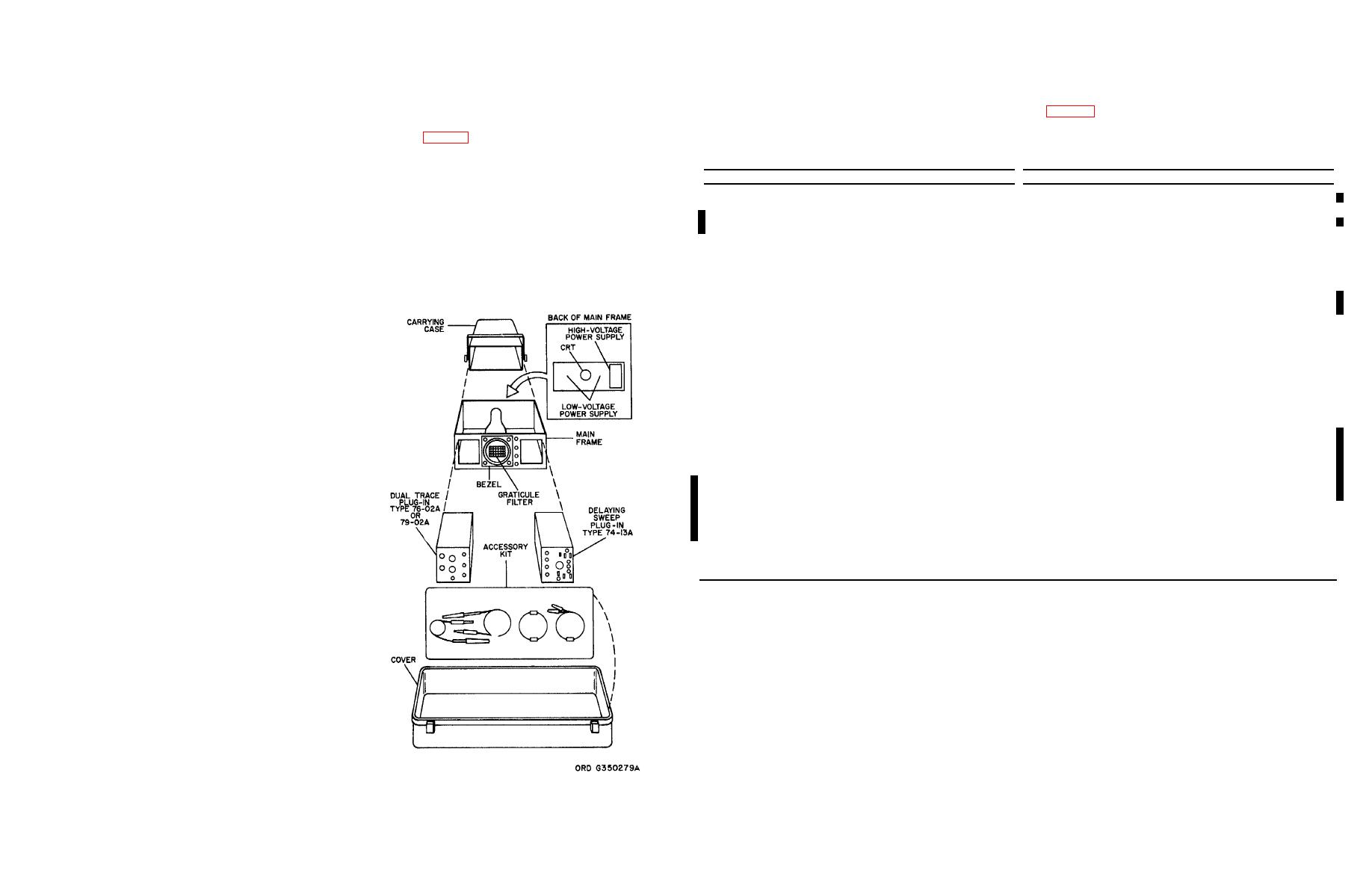
a. Complete Unit. There are three assemblies in the oscilloscope (Fig. 1-2). These are: the main frame, the dual
trace plug-in, and the delaying sweep plug-in. In addition, there is an accessory kit located inside the cover.
Table 1-2. Oscilloscope Operation and Maintenance Data
b. Main Frame. The main frame is a metal structure that mounts the cathode-ray tube (CRT) and the power
Item
Data
Item
Data
supplies. It has a cavity on each side for holding the dual trace and delaying sweep plug-in's. The low-voltage and high-
Power Requirements
Minimum external
0.5 volt peak-to peak (dc
voltage power supplies are located on the rear plate, and the CRT, which spans the whole structure, is located in the center of
Power
230 watts
trigger (X1 probe)
to 1 MHz) or 1.0 volt
Voltage
105 to 125 vane or 210 to
peak-to-peak (up to
the main frame. Both of these items are accessible by removing the fiberglass case. The CRT screen is covered by a
250 vac (at 60 Hz)
10 MHz)
neutral, circularly-polarized filter with a 6 by 10-centimeter graticule for measuring the displayed waveform. The filter is held in
48 to 1000 Hz
External trigger input
1 megohm, shunted by
place by an aluminum bezel. It is mounted on the front panel of the main frame which also mounts five CRT controls.
Temperature Limits
40 pf nominal
Delay
250 nsec to 20 sec
Storage
-40 to +85C
c. Dual Trace Plug-In and Delaying Sweep Plug-In.
These two plug-in units are physically and functionally
Dual Trace Plug-In
(-40 to 185F)
interchangeable. However, there is no provision for coupling an unblanking pulse from the left-hand plug-in to the CRT, so
Operating
-30 to 60C
when a vertical sweep is used, the trace is not blanked between sweeps. Each plug-in is constructed with guide rails to
Dc coupled
Dc to 25 MHZ own
(-22 to +140F)
provide for accurate insertion into the main frame cavity. Guide pins assure proper mating of the male connector with the
db at 25 MHZ
Humidity
40C (104F), 95%
female connector located on the rear plate of the main frame.
Ac coupled
10 Hz
relative humidity
External trigger input
1 megohm, shunted by
Altitude Range
40 pf
Note. Dual trace plug-in 79-02A is to he used for Y
Operational
15,000 ft
Rise time
15 nsec, driven from
deflection (in the left cavity) only.
Non-operating
50,000 ft
25-ohm source
CRT
Sensitivity
5 mv div to 25 volts div
Fluorescence color
Green
d. Accessory Kit. The accessory kit consists of
Dual trace Plug-In
Light transmittal
52%
the following:
79-02A
Persistence
70 sec
Bandwidth (3 db points)
Accelerating potential
13 kv
(1) Two attenuator probes X10 (probe assembly
Dc coupled
X axis direct input
10 to 15 volts/cm
7999B, test prods 4299B, or probe assembly 7994B).
X1 position
0 to 100 MHz
Y axis direct input
2.5 to 3.5 volts/cm
X10 position
0 to 90 MHz
Delaying Sweep
Ac coupled
Note. Probes 7999B or 7994B are for oscilloscope
Plug-In
X1 position
16 Hz to 100 MHz
765-MH/F, while probe 4299B is for the 765MH.
Sweep rate
10 nsec div to 5 sec div
X10 position
16 Hz to 90 MHz
Bandwidth (dc coupled)
Dc to 2 MHz, down 3 db at
Note. Response to frequencies as high as 250 MHz is
2 MHz
(2) Two sets of tip adapters (three per set
possible.
Minimum trigger rate:
(probe test kit 50288561).
Sensitivity
10 mv/div to 50 v/div
Ac coupling
80 Hz
Accuracy (voltage
3%
Afc coupling
10 kHz, with a minimum
(3) One connecting cable, BNC-to-alligator clip
measurements)
of 100 sec rise or fall
(test lead 50288581, type 7083).
Input impedance
1 megohm shunted by
time
14 pf nominal
(4) Two connecting cables, BNC-to-BNC to rf
cable assembly 50288581, type 7082).
1-9. Capabilities
(5) Two terminators, 50-ohm, 2 watt (dummy
The oscilloscope displays waveshapes of sampled electronic signals. It incorporates two major features: dual trace and
load 4285A).
delayed sweep.
(6) Two UG1090/U binding-post-to- BNC male
a. Dual Trace. The dual trace feature allows you to view two separate signals at the same time. This could be useful,
connectors 0903640, type 7080.
for example, in comparing the time delay of two logic inputs, or the before-and-after effects of a squaring circuit.
(7) Power cable 50301390.
b. Delayed Sweep. The delayed sweep feature permits you to select and expand one segment of the displayed signal.
For instance, you can measure the rise time of one pulse in a train of several.
Figure 1-2. Components of oscilloscope.
1-2.1
