
TM 9-6625-1753-14
C3
d. Voltage Regulators.
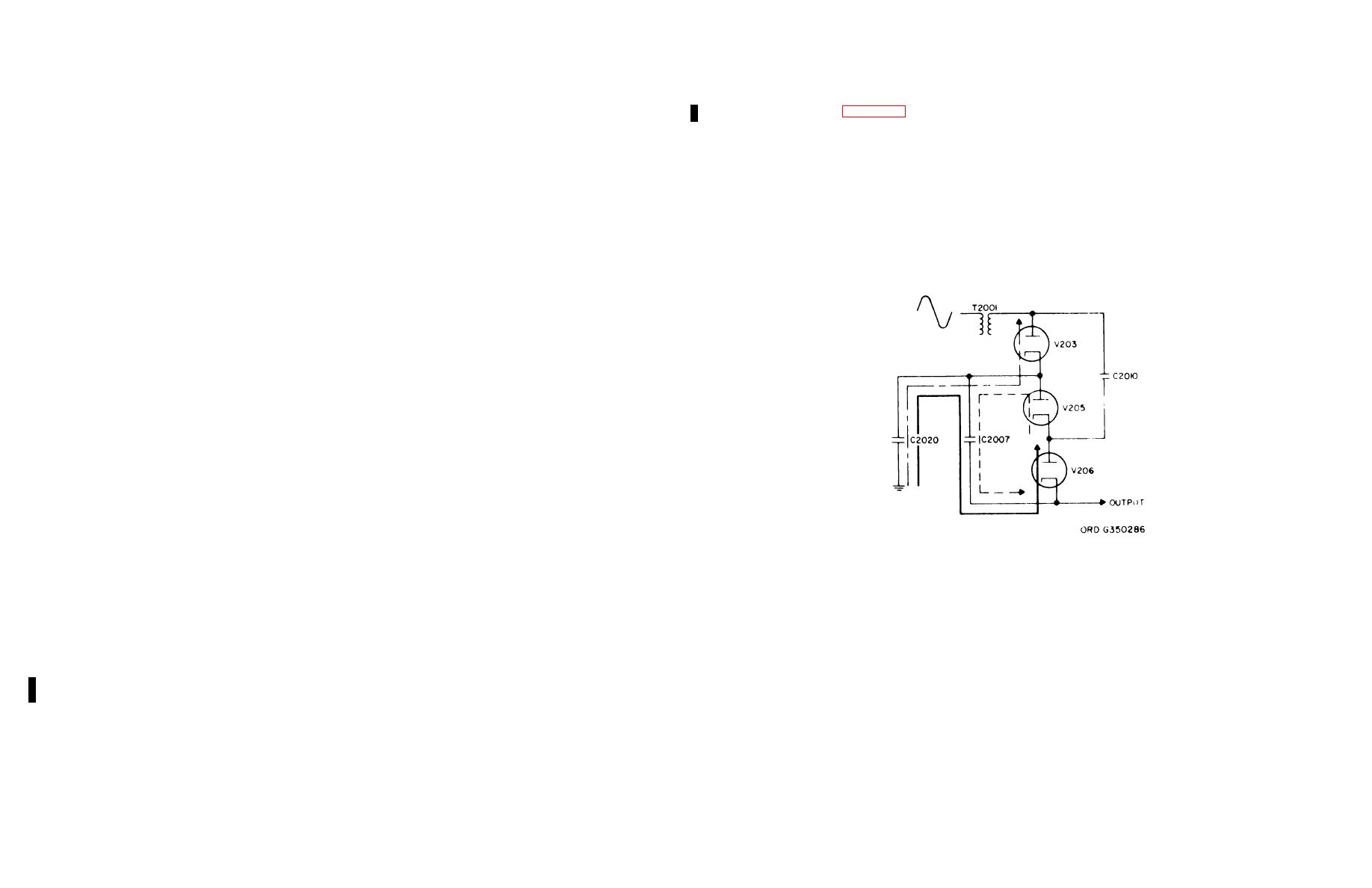
(1) Voltage tripler. Rectifiers V203, V205, and V206 make up a voltage tripler. (In later models this circuit consist of
(1) -50 Volts.
solid-state diodes CR2050, CR2051, and CR2052).
(a) The -50-volt regulator (zones D4, D5) is the master regulator to which all the other regulators in the power
(a) Looking at figure 3-1.1, assume that the positive half of the sine wave from transformer T2001 is applied to
supply are referenced. Therefore, if we are to maintain good regulation from the other power supplies, the -50-volt regulator
the circuit. Tube V203 is forward-biased and therefore conducts. Capacitor C2020 charges to approximately the peak
must be accurate.
voltage (E) via V203, as shown by the long-and-short dashed line in the figure.
(b) The main reference source is voltage regulator (gas-filled tube) V101. In normal operation the firing potential
(b) The positive cycle from T2001 is also applied to tube V206 via capacitor C2010.
of the tube is exceeded, resulting in a constant voltage drop across the tube. Resistor R1038 limits the current through the
This causes the tube to conduct and capacitor C2007 to charge to approximately the peak voltage (E) via C2020 and V206,
tube to a value within its operating range. If the output of the -50-volt rectifier varies, the tube current will in turn vary. The
as shown by the solid line in the figure. Since C2020 and C2007 are in series, and each is charged to approximately E, their
variation in current through the tube results in an increased or decreased voltage drop across resistor R1038, thus
resultant sum is 2E.
maintaining the tube's constant voltage characteristic.
(c) When the output of T2 001 goes negative, V203 cuts off. This negative voltage via C2010 also cuts off V206.
(c) This constant voltage is applied to -50V ADJ variable resistor R1041, and to resistors R1039 and R1042
Notice that this negative voltage forward-biases tube V205, causing it to conduct. With V205 conducting, capacitor C2007
which are all in series, forming a voltage divider across the tube. The wiper of R1041 takes a portion of the constant voltage
receives an additional charge of approximately E via V205, as shown by the short-dashed line in the figure. Notice that
and applies it to the base of Q114 in the difference amplifier.
C2007 is now charged to 2E and C2020 is charged to E. The sum of these two charges is of course equal to 3E, and is
(d) The other input to the difference amplifier comes from the rectified output of CR1007-CR1008, which is
approximately equal to the output voltage. Because of the high frequency involved capacitor C2007 and C2020 do not
filtered by C1018 and R1037. The negative output is applied across a voltage divider (R1049, R1048)(zone D15) to ground,
discharge appreciably between alternate half cycles.
and a portion of this fixed voltage drop is applied to the base of Q116 in the difference amplifier. Should the output voltage
from the rectifier begin to change, the variation is sensed by the difference amplifier and is applied to error driver (emitter
follower) Q115.
(e) Driver Q115 couples the error voltage to the base of emitter follower Q117, which acts as a controlled series
element. The series element conducts more or less current, depending on the original variation. By adjusting -50V ADJ
variable resistor R1041, you can set the regulated output voltage to exactly -50 volts.
(f) Breakdown diode CR1014 is a protective device. It conducts, shunting the excess current directly to ground,
before the breakdown voltage of series-element transistor Q117 is exceeded.
(2) 50 Volts. The only significant difference between the -50- and 50-volt regulators is that the 50-volt regulator uses
an error amplifier (Q112) instead of a difference amplifier. By adjusting +50V ADJ variable resistor R1035 (which is
connected to the -50 vdc regulated, reference point, output) to the proper bias for the error amplifier, a condition is set up
where any variation in voltage is sensed by the amplifier. The error voltage is then applied through error driver Q111 to
series-element transistor Q113. The resulting output is a regulated 50 volts with respect to ground. Breakdown diode
CR1013 is a protective device similar to CR1014 described above.
(3) 100 Volts. The 100-volt regulator is identical to the 50-volt regulator except that its negative terminal is connected
to the 50-volt regulated output (zone C6). +100V ADJ variable resistor R1024 is referenced to the -50 volts regulated output
(zone D6) and is adjusted for a regulated output of 100 volts.
(4) 200 Volts. This regulator is similar to those described above, except that the error amplifier uses two transistors
(Q104, Q105). The reference voltage, derived from the -50-volt regulated output, is taken from +200V ADJ variable resistor
R1015 and applied to the base of Q105. The emitter of Q105 is referenced to 100 volts regulated output via CR1010. The
output of Q105 then becomes the reference level for amplifier Q104. A portion of the output voltage is applied to the base of
Q104 via voltage divider R1012, R1013. Amplifier Q104 senses any change in voltage and couples it to driver Q103. The
Figure 3-1.1. Voltage tripler.
output from the driver goes to series element Q106, which compensates for the voltage change by passing more or less
current. Notice that the collector current for Q103 and Q106 is supplied by error driver Q101 and series element Q102.
(2) Negative 1350 volt supply. An ac voltage from the secondary tap of T2-01 is applied to half-wave rectifier
These two transistors increase the current capability of the 200-volt regulator, insuring greater stability.
CR2001 (zone D2), which passes only the negative half cycles. This is then filtered to become the -1350-vdc supply.
Breakdown diodes CR1009 and CR1011 protect the series-element transistors by conducting when a short circuit occurs.
c. High-Voltage Regulation. The -135p volts is applied through a resistor network to, HV ADJ variable resistor R2009R.
e. Calibration Voltage (1V P-P). A portion of the ac voltage from one of the secondaries of T1001 is applied to R1026
By adjusting R2009R, which has its ends connected to the 100-vdc regulated and 200-vdc regulated supplies, you can control
and transistor Q118, which functions as a switch. Q118 saturates when the ac voltage begins to go positive, producing an
the input bias at the control grid (pin 7) of V201A to -51 volts. This is the bias necessary for the stable operation of the high-
output that is near ground potential. When the ac voltage swings negative, Q118 immediately cuts off, and resistors R1052,
voltage oscillator. If the -1350-volt potential varies, the bias to V201A is affected. This variation produces a change in the
R1053, and R1054 reduce the collector voltage to 1 volt. This fast switching action of Q118 results in a 1-volt peak-to-peak
plate voltage of V201A which is coupled to the grid of V201B (pin 2). The output from V201 (pin 1) is applied to the screen
square wave for use in calibrating the oscilloscope (zone C3).
grid (pin 9) of Hartley oscillator V202, causing its conduction to change. The variation in conduction of V202 causes the
output frequency of the oscillator to change. The variation in frequency is related to output voltage. That is, as the tube
3-5. High-Voltage Supply (Older 765MH Models)
conducts more heavily the frequency increases, and as the frequency increases the output (negative) voltage increases.
Since this increased negative voltage is applied to the grid of V201A, it has the effect of reversing the process. Decreases in
a. Oscillator. High-voltage oscillator V202 is a conventional shunt-fed Hartley oscillator which uses transformer T2001
output voltage also tend to reverse the process, but in the opposite direction. Therefore, the voltage output must stabilize at
and capacitor C2006 to form a tank circuit. The oscillator generates a 40-kc to 60-kc sine wave, that is stepped up via T2001
some value which may be established by adjusting R2009R.
and is applied to both the high-voltage rectifier and the -1350-volt half-wave rectifier.
b. High-Voltage Rectifier.
3-3
