
TM 9-6625-1753-14
C2
Section V. FUNCTIONAL THEORY-DELAYING SWEEP PLUG-IN
74-13A (X-DEFLECTION), NEWER VERSION
3-17.
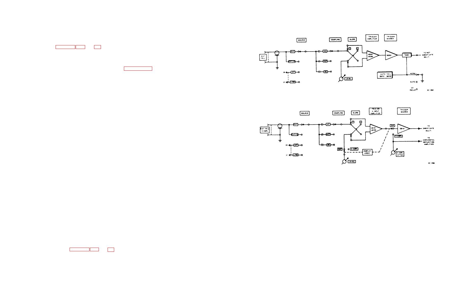
Trigger Circuit (Figs. 3-12, 3-13, and 6-4)
a. Normal and Delaying Triggering
(1) Since the input of the normal and delaying triggering circuit (NDT) is similar to that of delayed armed (DA) trigger
circuit, only the NDT circuit will be discussed in detail. Refer to paragraph 3-23 for a description of the X input circuit. The
input to trigger amplifier V8201 and V8202 may be selected from one of three sources via the trigger SOURCE switch as
follows:
(a) In EXT or EXT/10 position, the signal is obtained from an external source through the EXT TRIG front-panel
connector.
Figure 3-12. NDT trigger circuit, functional block diagram.
(b) In INT position, the signal is derived from the Y plug-in unit.
(c) In LINE position, the signal is tapped from one side of the 6.3-vac heater circuit.
(2) A choice of AC, ACF, or DC coupling is provided by the COUPLING switch. In the AC position, the trigger signal
is applied to a high-pass filter consisting of C8203, C8205, and R8207, providing a low-frequency cutoff of 80 cycles. The
low-frequency cutoff is raised to 10 KHz in the ACF position, and the high-pass filter now has R8204 shunting R8207. In the
DC position, the high-pass filters are disconnected and the triggering signal is applied directly to the trigger amplifier. The RC
network, R8206 and C8202, in series with the grid of V8201 or V8202, protects the input circuit from damage due to excessive
input voltage. Shunt capacitor C802 across R8206 preserves the high-frequency signal component.
(3) The negative pulse at the output of the trigger amplifier occurs only when there is a positive-going signal at the
input. However, it is desirable to start the sweep during either a positive-going or negative-going portion of the excitation
signal. To accomplish this, the SLOPE switch is used to select the desired polarity of the triggering signal.
(4) For positive-going signals, connection is made to the grid of V8201, and for negative-going signals, connection is
made to the grid of V8202. In each case, the opposite grid is connected to a dc bias source, adjustable by means of LEVEL
Figure 3-13. DA trigger X input circuit, functional block diagram.
control R8222. This control is used to select the level of the triggering point for all settings of the SLOPE switch.
from the shaper circuit. Diode CR8203 and the lockout circuit hold off subsequent triggering signals until after the sweep and
(5) The output from V8201 or V8202 is applied to trigger shaper Q8202, which drives trigger coupling transformer
retrace are completed. In the quiescent state, Q8206 is conducting and Q8207 is at cutoff. Q8206 forms a positive gate while
T8201. The resulting negative trigger is applied to series coupling diode CR8203 to the base of the delaying sweep gate
Q8207 forms a negative gate during the forward sweep interval.
multivibrator.
(2) CR8203 serves as a low-capacitance coupling diode which couples the negative trigger from the shaper circuit to
(6) TRIG SENS adjustment R8229 sets the tunnel diode trigger at its optimum sensitivity. TRIG BAL adjustment
the sweep gate multivibrator, which flips and initiates the sweep. CR8203 also serves as a high back-impedance diode to
R8234 sets the level of V8201 and V8202 through tunnel diode CR8201, so that no readjustment of the LEVEL control is
decouple the trigger shaper from the sweep gate multivibrator. After the bistable multivibrator has been triggered, the sweep
required when the SLOPE switch is set from plus to minus slopes or vice versa. This adjustment is made when the LEVEL
runs up. When the saw reaches full screen deflection, turn-off diode CR8204 conduct and resets multivibrator Q8206 and
control is set to zero.
Q8207, which then clamps the saw. SWP LENGTH variable resistor R8253 is adjusted for full-screen sweep length display.
b. Automatic Triggering. When the NORM-AUTO-HF RECUR toggle switch is set to AUTO, the trigger circuit is
b. Saw Generation.
ungrounded and becomes activated. Application of a trigger signal from 10 Hz to 10 MHz switches the sweep immediately to
the triggered mode. This technique insures stable synchronization of the desired input signal. The auto trigger multivibrator
(1) The saw generator is of the Miller "run-up" type. The negative output developed at the collector of Q8207 is
reverts to its natural mode in about 1 second after the discontinuance of the trigger excitation signal. Consequently, a
applied to the anodes of disconnect diodes CR8205, CR8209, CR8211, and CR8216. The anode voltages of these diodes no
horizontal reference trace will appear on the screen even in the absence of an input signal.
longer conduct. This action unlocks the integrator clamp and permits the selected sweep capacitor to charge linearly through
the associated resistance network.
3-18.
Normal Sweep Circuit (Figs. 3-14, 3-15, and 6-4)
a. Delaying Sweep Gate Multivibrator.
(1) The input triggering signal is applied to the base of transistor Q8206, through series-coupling diode CR8203. The
dc-coupled bistable multivibrator, Q8206 and Q8207, initiates the formation of the sweep after receiving a negative trigger
3-15
