CRT base. (Align the two holes in the cover to the holes
c. Connect the voltmeter between pin 14 of the CRT base
inthe socket),
socket and chassis ground. (See Fig. 6-6). Set the voltmeter
range to measure approximately 4000 volts.
o
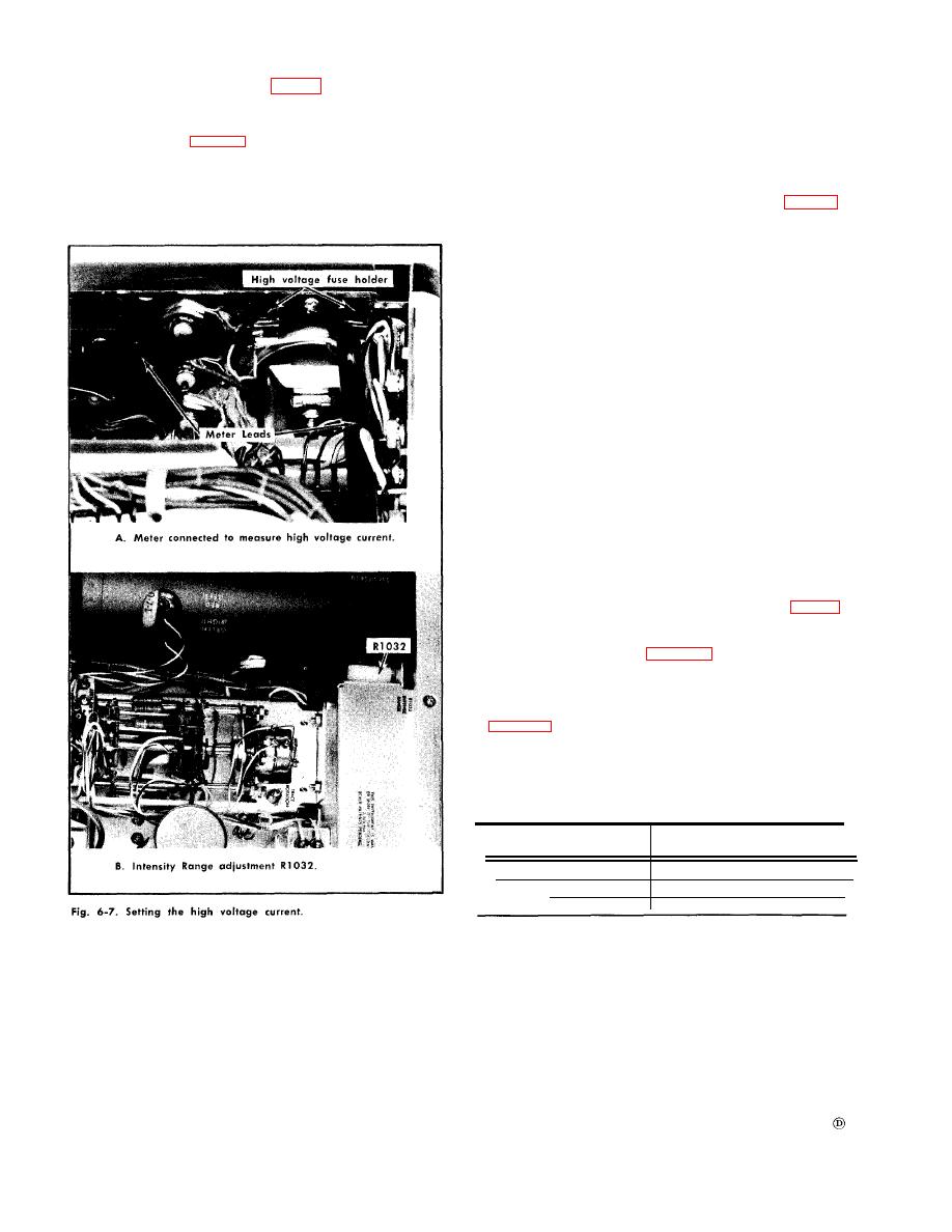
4. Adjust Intensity Range
d. Turn the POWER switch to ON and adjust the High
a. Test equipment setup is given in step 3.
Voltage Adj R1000 (Fig. 6-6) for a meter reading of 3670
volts.
b. Turn the POWER switch to the OFF position, then
remove the high voltage fuse F1008.
e. Turn the POWER switch to OFF, remove the meter lead
probes and replace the plastic protective cover over the
c. Connect an ammeter across the fuse holder (Fig. 6-7)
Set the ammeter range to 1A.
d. Turn the vertical POSITION control fully counterclock-
wise to position the beam off the CRT screen, turn the
POWER switch to ON and the INTENSITY control fully
clockwise.
NOTE
Be careful not to exceed 800 mA meter reading.
If the Intensity Range is misadjusted, the current
may exceed 800 mA and blow the high voltage
fuse.
e. Adjust the Intensity Range R1032 for a current read-
ing of 750 mA.
f. Turn the POWER switch to OFF, remove the meter
leads and replace the high voltage fuse. Check that the
fuse is a 1A fast blow. Turn the POWER switch to ON, then
readjust the INTENSITY and POSITION controls for a cen-
tered trace of nominal brightness.
5. Check Power Supply Voltage Regulation and
Ripple Amplitude
a. Test equipment setup is given in step 4.
b. Connect the VOM to the voltage check paints (Fig. 6-5),
and check the voltage regulation of each regulated supply
as the input line voltage is varied through the input line
voltage range as shown in Table 6-1.
Connect the 1 probe from the test oscilloscope to the
voltage check points and note the ripple amplitude. Volt-
age regulation and typical ripple amplitudes are listed
in Table 6-2.
The input line voltage to the Type 491 is adjusted by
means of the autotransformer which is connected between
the source and the Type 491 input power connector.
Line Voltage
Input Voltage Range
Selector
LOW
90-110 VAC
MED
104-126 VAC
112-136 VAC
HIGH


