
TM 11-6625-2781-14&P-2
Section IV
PERFORMANCE TESTS (cont'd)
4-26. Frequency Response (cont'd)
ANALYZER Control Settings (cont'd)
LINEAR SENSITIVITY ................................ ................................ ................................ ............................... 2 mV/DIV
VIDEO FILTER ................................ ................................ ................................ ................................ .................. OFF
SCAN MODE ................................ ................................ ................................ ................................ ....................... INT
SCAN TRIGGER ................................ ................................ ................................ ................................ ............ AUTO
608E/F:
MODULATION................................ ................................ ................................ ................................ .................... CW
ATTENUATION ................................ ................................ ................................ ................................ ........... -30 dBm
MEGACYCLES................................ ................................ ................................ ................................ ..................... 10
FREQUENCY RANGE................................ ................................ ................................ ................................ ............ A
AMPL TRIMMER ................................ ................................ ................................ ........Press and peak meter reading
8405A:
FREQUENCY RANGE - MHz ................................ ................................ ...Setting compatible with 608E/F frequency
CHANNEL ................................ ................................ ................................ ................................ .............................. A
AMPLITUDE RANGE - dB ................................ ................................ ................................ ................................ ... -30
2. Adjust the analyzer FREQUENCY control to place 10 MHz input signal on the far left (-5) graticule line. Adjust
LINEAR SENSITIVITY vernier for 7 divisions signal amplitude.
3. Tune the 608E/F signal generator from 10 MHz to 110 MHz keeping its amplitude constant by monitoring the 8405A
RF Voltmeter. Be sure to peak the 608E/F AMPL TRIMMER when changing ranges. Note the frequency at which
the analyzer response is maximum and reset the display amplitude at this frequency to 7.4 divisions. The frequency
response of the analyzer should be between 6.6 and 7.4 divisions from 10 MHz to 110 MHz.
6.6
7.4 DIV
4. Note the display amplitude at 10 MHz.
6.6
7.4 DIV
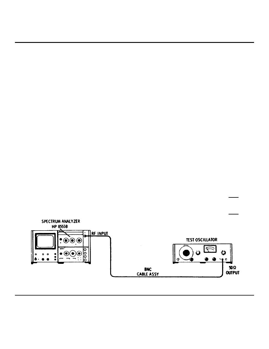
Figure 4-10. Frequency Response Test: 1 kHz to 10 MHz
4-14
