TM 11-6625-2781-14&P-2
Section IV
PERFORMANCE TESTS (cont'd)
4-24. Scan Width Accuracy (cont'd)
1.
Connect the test setup in Figure 4-5 and make the following control settings:
ANALYZER
RANGE MHz ................................ ................................ ................................ ................................ ................... 0-110
FREQUENCY ................................ ................................ ................................ ................................ ............... 60 MHz
BANDWIDTH ................................ ................................ ................................ ................................ ............... 300 kHz
SCAN WIDTH ................................ ................................ ................................ ................................ ....PER DIVISION
SCAN WIDTH PER DIVISION ................................ ................................ ................................ ...................... 10 MHz
INPUT ATTENUATION................................ ................................ ................................ ................................ ...... 0 dB
SCAN TIME PER DIVISION ................................ ................................ ................................ ........ 2 MILLISECONDS
LOG REF LEVEL ................................ ................................ ................................ ................................ ......... -20 dBm
VIDEO FILTER ................................ ................................ ................................ ................................ .................. OFF
SCAN MODE ................................ ................................ ................................ ................................ ....................... INT
SCAN TRIGGER ................................ ................................ ................................ ................................ ............ AUTO
LOG-LINEAR ................................ ................................ ................................ ................................ ..................... LOG
8406A
COMB FREQUENCY - MC ................................ ................................ ................................ .............................. 10 Mc
INTERPOLATION AMP ................................ ................................ ................................ ................................ ..... OFF
OUTPUT AMPLITUDE................................ ................................ ................................ ................................ .3 o'clock
2.
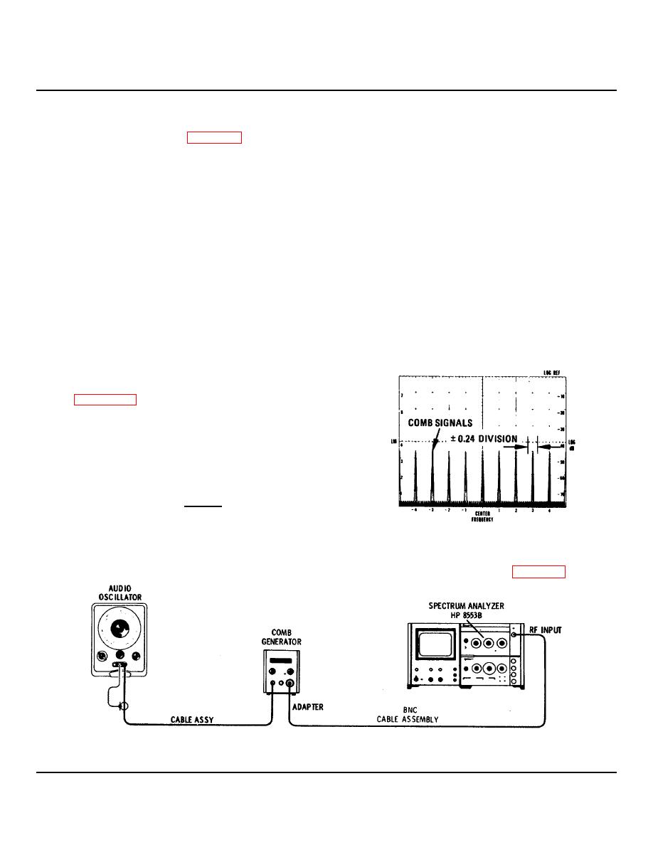
With control settings as in step 1 above, a comb
signal occurs every 10 MHz on the display (see
TUNE to line up a comb signal with the far left
graticule line.
3.
Measure the amount of error, in divisions, that
the comb signal deviates from the +3 graticule
line. The comb signal should occur on the +3
line +0.24 divisions.
+2.76
+3.24 (on display)
Figure 4-6. Scan Width Accuracy Measurement
4.
To test .05 MHz SCAN WIDTH PER DIVISION setting, connect test equipment as shown in Figure 4-7.
Figure 4-7. Scan Width Accuracy Test: .05 MHz/Div
4-9


