TM 11-6625-2781-14&P-2
Section IV
PERFORMANCE TESTS (cont'd)
4-30. Noise Sidebands
SPECIFICATION:
More than 70 dB below CW signal 50 kHz or more away from signal, with a 1 kHz IF BANDWIDTH setting.
DESCRIPTION:
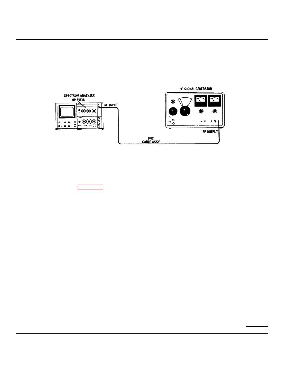
A stable -40 dBm CW signal is applied to the spectrum analyzer and displayed on the CRT. The amplitude of the noise
associated sidebands and unwanted responses close to the signal are measured.
Figure 4-14. Noise Sideband Test
EQUIPMENT:
Signal Generator................................ ................................ ................................ ................................ ......... HP 606B
BNC Cable Assembly................................ ................................ ................................ .............................. HP 10503A
1. Connect the test setup in Figure 4-14 and make the following control settings:
ANALYZER
RANGE MHz ................................ ................................ ................................ ................................ .................. 0 -110
FREQUENCY ................................ ................................ ................................ ................................ ............... 40 MHz
BANDWIDTH ................................ ................................ ................................ ................................ ................... 1 kHz
SCAN WIDTH ................................ ................................ ................................ ................................ ....PER DIVISION
SCAN WIDTH PER DIVISION ................................ ................................ ................................ ....................... 10 kHz
SCAN TIME PER DIVISION ................................ ................................ ................................ ................... 1 SECOND
INPUT ATTENUATION................................ ................................ ................................ ................................ ...... 0 dB
LOG REF LEVEL ................................ ................................ ................................ ................................ ......... -40 dBm
TUNING STABILIZER................................ ................................ ................................ ................................ .......... ON
VIDEO FILTER ................................ ................................ ................................ ................................ .............. 100 Hz
SCAN MODE ................................ ................................ ................................ ................................ ....................... INT
SCAN TRIGGER ................................ ................................ ................................ ................................ ............ AUTO
LOG/LINEAR ................................ ................................ ................................ ................................ ..................... LOG
606B
FREQUENCY ................................ ................................ ................................ ................................ ............... 40 MHz
ATTENUATOR ................................ ................................ ................................ ................................ ............ -40 dBm
MOD SELECTOR ................................ ................................ ................................ ................................ ................. cw
2
Tune the analyzer to center the display, and if necessary, adjust HP 606B output vernier so that the signal amplitude
peaks at the top graticule line.
3. Observe the noise level five divisions or greater away from the signal (50 kHz). The average noise level should be
at least 7 divisions below the signal level.
Noise Level >7 div below carrier level:
4-20


