
TM 11-6625-255-14/TO 33A113-170-1
arm. When the bridge is adjusted to reject a given
knobs, one for coarse FREQUENCY settings of
fundamental frequency, RC 1 must be equal to
the capacitor and one for fine FREQUENCY ad-
RC 2, and R, must be equal to two times R 2. It can
justments. Capacitor C13 is used to select the ex-
be seen from the graph that the skirt rejection
act rejection frequency of the bridge.
characteristic of the bridge does not have a steep
e. The bridge is never physically disconnected
slope.
from the circuit. Operation of function switch S4A
b. When the bridge is inserted as the interstage
to SET LEVEL or NOISE places a ground at the
coupling element in an inverse feedback amplifier,
junction of the series reactive arm and shunt reac-
the rejection characteristics of the bridge are
tive arm (fig. 6-7). This action disables the fre-
greatly improved. When the bridge is used in this
quency rejection characteristic of the bridge.
way, the phase, as well as the amplitude response,
6-4. Bridge as Frequency Rejection Filter
can be used. Figure 6-5 shows how the rejection
characteristics of the bridge are improved when
a. The sharp frequency rejection property of
the bridge is inserted as the coupling component
the bridge is obtained from the combined char-
in a feedback amplifier. The feedback amplifier
acteristics of the resistance-capacitance networks
attains maximum negative feedback when the re-
in the bridge and vacuum-tube circuits contained
turned function of the output signal is impressed
in the preamplifier and bridge amplifier. Figure
at the input circuit in opposite phase to the
original signal. This condition exists only for the
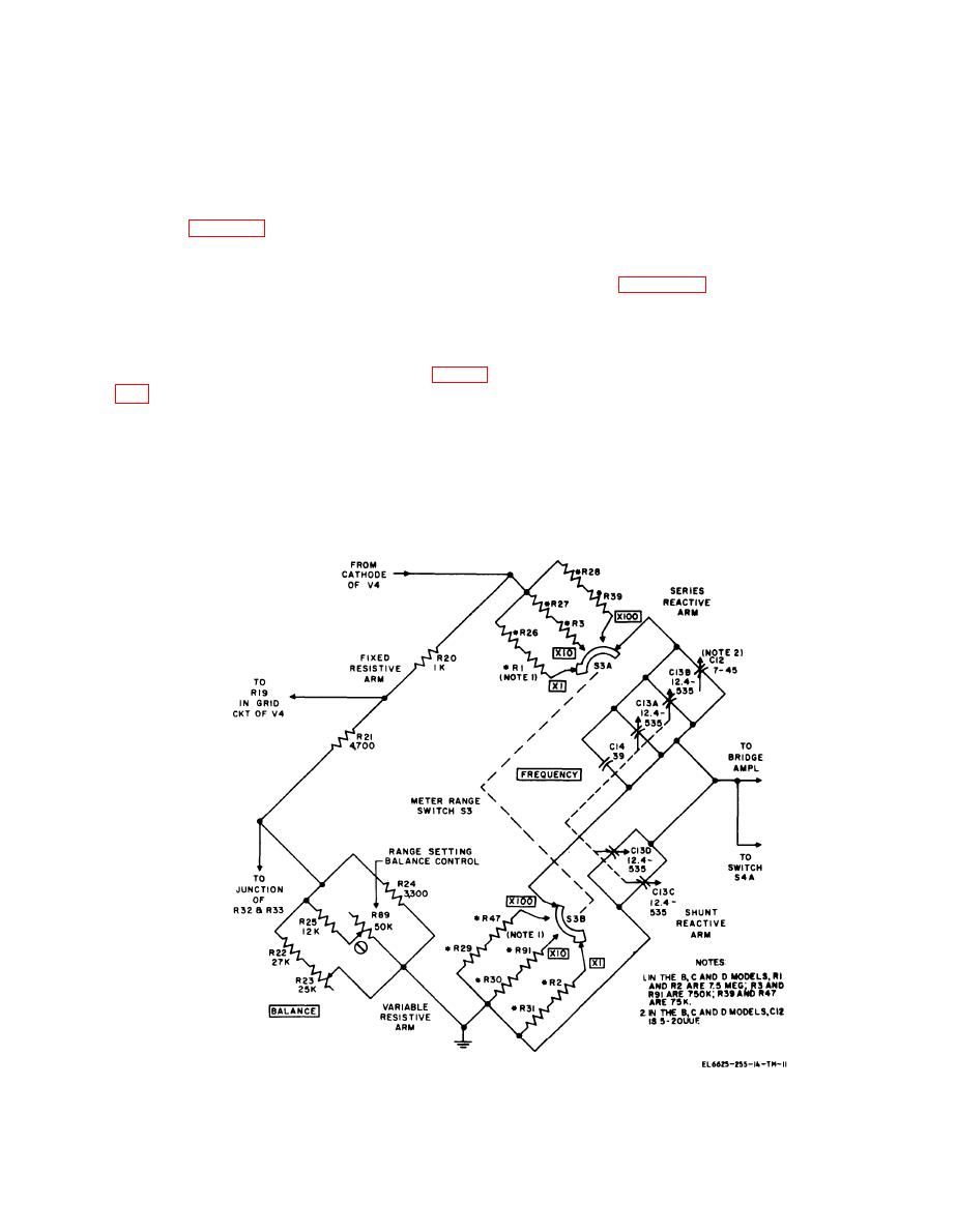
of the bridge. The equivalent circuit diagram of
frequency being rejected (fo) as illustrated in fig-
the bridge shows the conditions that exist in the
ure 6-6 because the bridge imparts considerable
bridge to give the frequency rejection characteris-
phase shift to other frequencies.
tics shown in the graph. RC 1 represents the series
reactive arm of the bridge, RC 2 represents the
c. Only V2 and V3 produce 180 phase dis-
placements. This action establishes proper phase
shunt reactive arm, R 1 represents the fixed resis-
orientation for the negative feedback loop. There
tive arm, and R 2 represents the variable resistive
Figure 6-3. Bridge circuit, simplified schematic diagram.
6-5
