
TM 11-25-255-14/TO 33A1-13-170-1
d. When S4A is set to NOISE, the bridge cir-
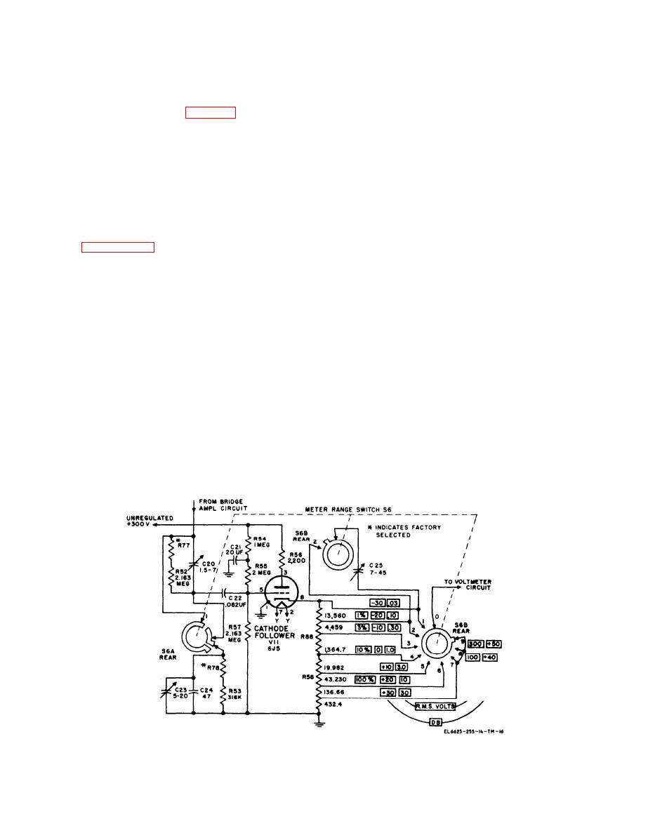
b. When S6 is set to .30, 1.0, 3.0, 10, or 30
cuit is shorted to ground so that the preamplifier
R.M.S. VOLTS, the incoming signals pass
through C22 to the grid of V11.
and bridge amplifier circuits operate as a straight
c. When S6 is set to .10 R.M.S. VOLTS,
five-tube amplifier with 40-dB gain. When S4A is
switch S6B brings trimmer C25 into the cathode
set to NOISE, switch S4B (fig. 6-2) is also auto-
circuit of V11. Trimmer C25 provides control of
matically set to NOISE since both switches are on
the high-frequency response for this voltage
the same shaft. This action brings NOISE GAIN
range.
control R5 and R6 into the negative feedback cir-
c u i t from V6, attenuating the feedback voltage
d. W h e n S 6 i s s e t t o 1 0 0 o r 3 0 0 R . M . S .
VOLTS, the incoming signals pass through net-
which, in turn, increases the gain of the amplifier
work R52 and R77 in parallel with trimmer C20
circuits. In this position, all incoming frequencies
before passing through C22 to the grid of V11.
are passed from the output of the bridge amplifier
For the 300 R.M.S. VOLTS setting, switch S6A
through the switch contacts to the vtvm circuit.
switches in network R53 and R78 in parallel with
6-7. Voltage Divider Circuit
C 2 4 and C23. Voltage divider R53, R78, R57,
R52, and R77 reduces the level of the incoming
schematic diagrams of the voltage divider circuit.
signal before it is passed through C22 to the grid
Tube V11 is a cathode follower with multisection
of V11. Trimmer C20 is used to adjust the high-
f r e q u e n c y response for the 100 R.M.S. VOLTS
series resistance connected in its cathode circuit.
Tube V11 and its accompanying circuitry provide
setting. Trimmer C23 is used to adjust the high-
f r e q u e n c y response for the 300 R.M.S. VOLTS
a high input impedance for the vtvm section and
setting. Capacitor C24 reduces the effect of C20
m a k e possible adjustment of the frequency re-
sponse for different voltage ranges. Taps on the
on the high-frequency response for the 300
R . M . S . VOLTS setting.
c a t h o d e resistance are connected to the switch
e. Resistors R88 and R58 in the TS-723A/U
contacts of switch section S6B on the TS
- 7 2 3 A /U, or switch section S6C on all other
(R92 through R98 in all other models) form part of
the cathode biasing network. The net grid bias is
models. Meter range switch S6 has nine positions
for selecting various voltage and dB ranges.
d e t e r m i n e d by the combination of the cathode
resistance and R57 in conjunction with the series
combination of R54 and R55. Resistor R54 is also
NOTE
used in combination with C21 to form a filter to
I n the TS-723A/U, the cathode resist-
i s o l a t e the grid circuit from the power supply.
ance is composed of multisection resis-
Resistor R56 is connected to the plate of V11 to
tors R58 and R88. In all other models,
improve the frequency response. At high frequen-
the resistance is made up of R92
cies, R56 is partially bypassed by tube and stray
t h r o u g h R98.
Figure 6-8. Voltage divider circuit, simplified schematic diagram, Spectrum Analyzer TS-723A/U.
6-8
