TM 11-6625-255-14/TO 33A1-13-170-1
input of V 12. Its function is to improve frequency
vides conduction for the negative portion of the ac
r e s p o n s e and to stabilize the operation of the
cycle. Tube V14A (CR2 of TS-723D/U) provides
vtvm circuit. The amount of feedback voltage es-
conduction for the positive portion of the ac cycle.
tablishes the gain of the voltage amplifier circuit.
Meter M1 is a milliammeter calibrated in R.M.S.
During the positive portion of the ac cycle, the
V O L T S and DECIBELS. The sensitivity of the
feedback loop is completed through R71. During
meter is 1,000 ohms per volts, or 1 milliampere for
the negative portion of the ac cycle, the feedback
full-scale reading. Capacitor C31 filters out the ac
loop is completed through R70. The amount of
component appearing across the meter terminals.
feedback voltage applied to the grid of V12 is
d. A negative feedback loop is obtained at the
g o v e r n e d by network R61, R62, and R63. The
o u t p u t of V14 (CR1 and CR2 of TD-723D/U).
variable resistor R62 VM GAIN is used to adjust
This negative feedback voltage is fed back to the
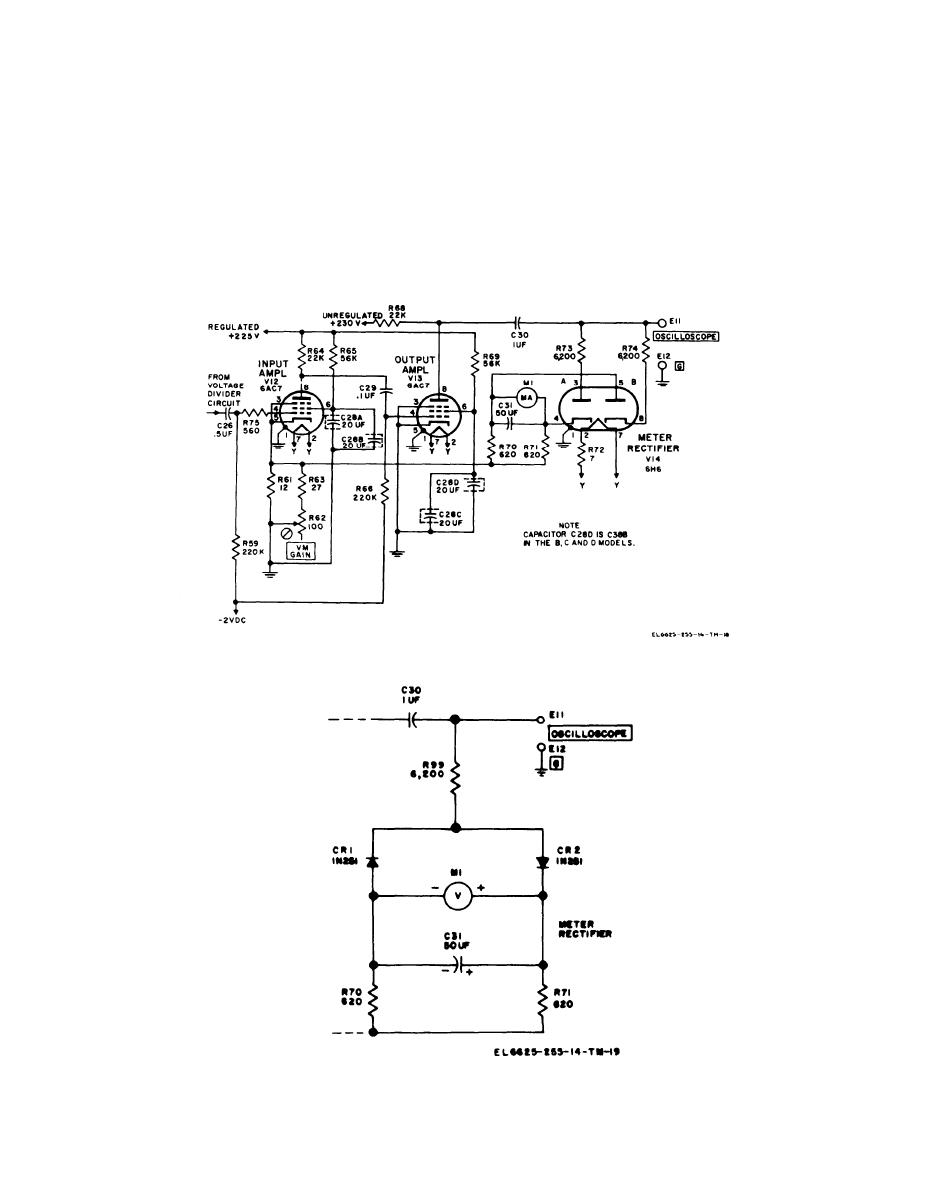
Figure 6-10. Voltage amplifier and meter circuit, simplified schematic diagram.
Figure 6-11. Meter rectifier circuit, Spectrum Analyzer TS-723D/U.
6-10


