
Section V
TM 11-6625-2781-14&P-2
ADJUSTMENT PROCEDURES (cont' )
d
5-29. APC Search Oscillator Checks (cont'd)
2. Dc-balance the oscilloscope, and set the base line at the center horizontal graticule.
3. Disconnect the lead from A6C1. Connect the oscilloscope input to A6C2.
4. Measure the waveform that appears at A6C2. Amplitude should be between 2.0 and 2.8 volts, peak-to-peak.
Waveform period should be 100 ms 25 ms.
Amplitude: 2.0 _______2.8 volts p-p
Period: 75 _______125 ms
5. Reconnect the green lead to A6C1.
6. Set the oscilloscope horizontal scale to 1 second per division. Monitor A6C2 while slowly turning the analyzer
FREQUENCY control.
7. As FREQUENCY is tuned slowly across the dial, the voltage at A6C2 should be 1.5 0.2 volts peak-to-peak.
1.3 ________1.7 volts p-p
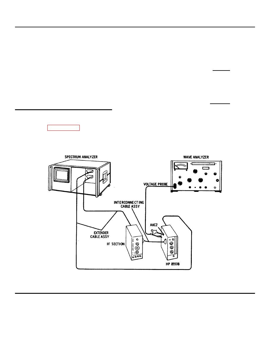
5-30. APC 100 kHz Rejection Adjustment
REFERENCE: Service Sheet 6.
DESCRIPTION: The APC search voltage output is monitored while adjusting the rejection control for minimum 100 kHz
signal.
Figure 5-14. APC 100 kHz Rejection Adjustment Test Setup
5-21
