
Section V
TM 11-6625-2781-14&P-2
ADJUSTMENT PROCEDURES (cont' )
d
5-28. APC Sampler Adjustment (cont'd)
ANALYZER Control Settings (cont'd)
SCAN WIDTH PER DIVISION ................................ ................................ ................................ ....................... 20 kHz
SCAN TIME PER DIVISION ................................ ................................ ................................ ...... 10 MILLISECONDS
A6 APC SEARCH ................................ ................................ ................................ ................................ ............ TEST
180A/1801A/1821A:
VERTICAL SCALE
Channel A ................................ ................................ ................................ ................................ . 0 2 VOLTS/DIV
Channel B ................................ ................................ ................................ ................................ . 0 1 VOLTS/DIV
VERTICAL COUPLING................................ ................................ ................................ ................................ ........ DC
HORIZONTAL SCALE ................................ ................................ ................................ .............................. 10 S/DIV
TRIGGER ................................ ................................ ................................ ................................ ................ lNTERNAL
211B:
FREQUENCY (Hz)................................ ................................ ................................ ................................ ................ 10
MULTIPLIER ................................ ................................ ................................ ................................ ........................ 1K
SYMMETRY ................................ ................................ ................................ ................................ ............... Centered
AMPLITUDE (V ACROSS 50 Ohms) ................................ ................................ ................................ ...................... 5
2. Dc-balance oscilloscope Channels A and B. Set the base lines to the center horizontal graticule line. Switch the
input to Channel A.
3. Adjust the square-wave generator AMPLITUDE
and SYMMETRY controls for a symmetrical, 0.8
volt peak-to-peak square wave.
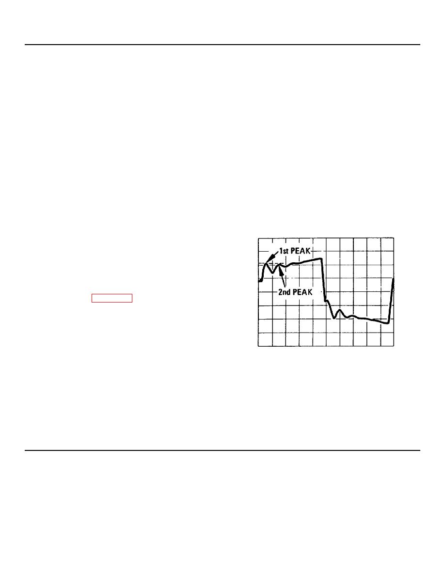
4. Switch the oscilloscope to Channel B. Adjust
SYMMETRY controls, and the oscilloscope
TRIGGER control for a steady, single waveform
as shown in Figure 5-12.
5. Dc-balance the waveform by adjusting
A6A1R13, the sampler BIAS adjust.
The
waveform should be balanced to zero volts 0.3
volts.
-0.3 _______+0.3V
Figure 5-12. APC Sampler Adjustment.
6. Adjust A6A1C16, the sampler Efficiency Adjust, until the first and second peaks are equal in am plitude.
Sampler Efficiency ________( √ )
7. Recheck the oscilloscope dc balance, and then reset the sampler bias adjust as in step 5, if necessary.
8. Set A6 APC SEARCH to NORMAL.
5-19
