
Section V
TM 11-6625-2781-14&P-2
ADJUSTMENT PROCEDURES (cont' )
d
5-27. 100 kHz Reference Oscillator Check (cont'd)
180A/1801A/1821A:
VERTICAL SCALE................................ ................................ ................................ ................................ . 1 VOLT/DIV
SWEEP TIME ................................ ................................ ................................ ................................ ......... 5SEC/DIV
INPUT................................ ................................ ................................ ................................ ................................ .. DC
6217A:
VOLTAGE ................................ ................................ ................................ ................................ ................ -12.6 VDC
2. Disconnect the -12.6 Vdc lead from A8C3.
Connect the 6217A Power Supply to A8C3. 2 U
SEC/DIV Set the output voltage to -12.6 Vdc.
3. Disconnect the 11592-60003 RF cable from
A8J1. Connect the white BNC-to-Selectro test
cable between A8J1 and the oscilloscope.
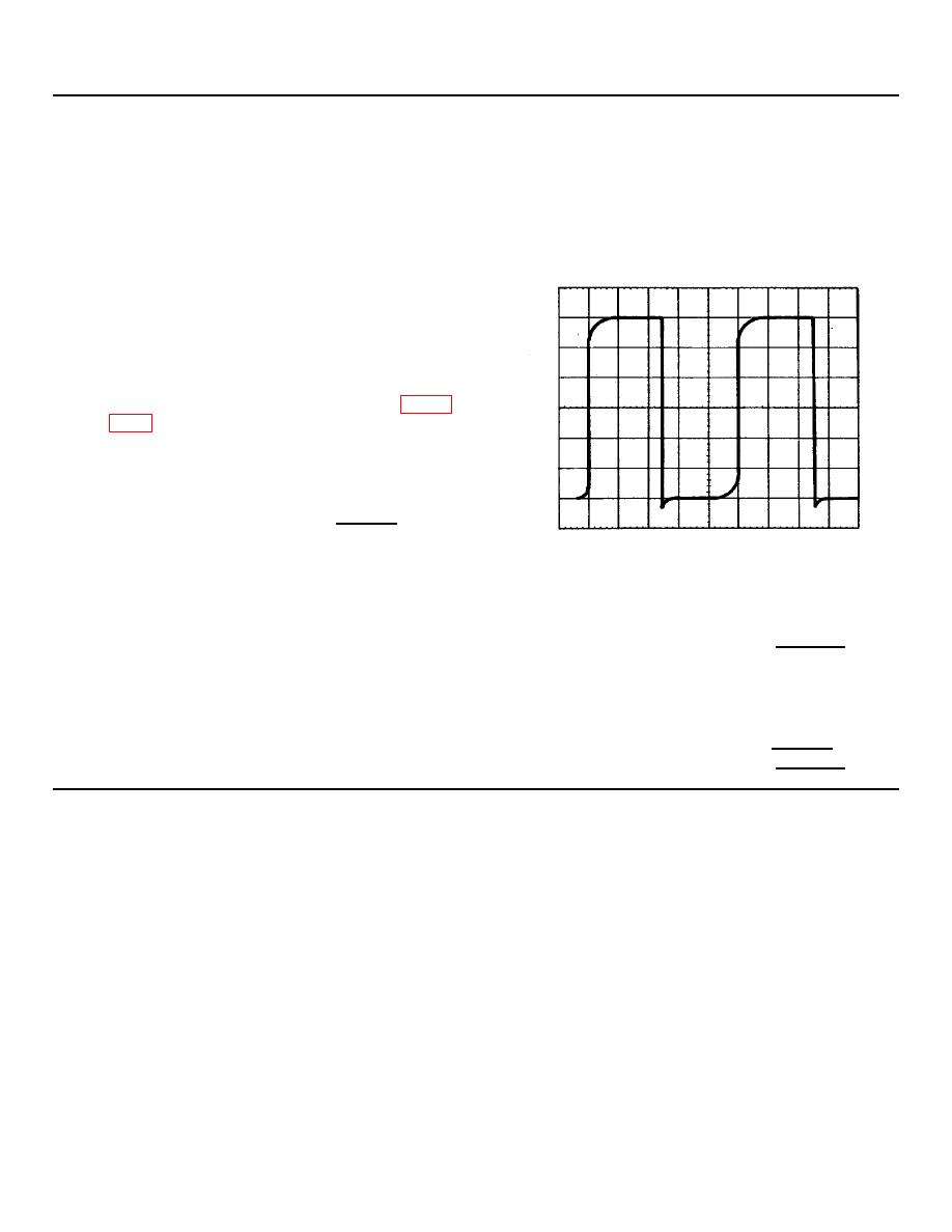
4. Measure the 100 kHz output signal. See Figure
peak-to-peak. Period of the waveform should
be 10 +0.5 seconds.
Amplitude: 5.6 ______6.4 V p-p
Period: 9.5 _______10.5 s
Figure 5-10. Reference Oscillator Output Measurement
5. Vary the power supply voltage between -10.5 and -14.5 Vdc while monitoring output on the digital voltmeter. The
100 kHz oscillator should maintain a period of 9.5 to 10.5 s as listed in step 4.
9.5 ________10.5 s
6. Disconnect the power supply from A8C3. Reconnect the analyzer -12.6 Vdc supply to A8C3.
7. Check amplitude and waveform period as in step 4.
Amplitude: 5.6 _______6.4 V p-p
Period: 9.5 ________10.5 s
5-17
