
Section VII
TM 11-6625-2781-14&P-2
PERFORMANCE TESTS (cont'd)
7-9. Average Noise Level (cont'd)
1. Check the analyzer to make sure it is vertically calibrated. Refer to Paragraph 4-12 for instructions. In
mV/div (2 mV x 1). Since the -30 dBm calibrator output is 8.66 mV (across 75 ohms), the CRT deflection should
be -4.33 div isions.
2. Make the following analyzer control settings:
RANGE MHz ................................................................................................................................................... 0-110
FREQUENCY ............................................................................................................................................... 30 MHz
BANDWIDTH ................................................................................................................................................... 1 kHz
SCAN WIDTH ................................................................................................................................................. ZERO
INPUT ATTENUATION ...................................................................................................................................... 0 dB
BASE LINE CLIPPER.......................................................................................................................................CCW
SCAN TIME PER DIVISION...................................................................................................... 50 MILLISECONDS
LOG REF LEVEL......................................................................................................................................... -50 dBm
LOG REF LEVEL vernier ........................................................................................................................................ 0
LOG-LINEAR .....................................................................................................................................................LOG
VIDEO FILTER .............................................................................................................................................. 100 Hz
SCAN MODE.......................................................................................................................................................INT
SCAN TRIGGER ............................................................................................................................................ AUTO
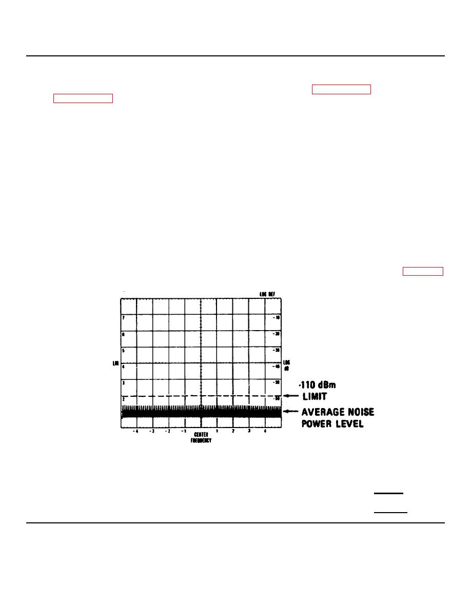
3. Observe the average noise power level on the CRT. It should be lower than -110 dBm as shown in Figure 7-1 .
Make sure the LOG REF LEVEL vernier is set at 0 during the measurement.
Figure 7-1. Sensitivity Measurement: CRT Display.
4. Set BANDWIDTH to 10 kHz, and repeat step 3. The average noise power level should be lower than -100 dBm.
-100 dBm
5. Set BANDWIDTH to 100 kHz, and repeat step 3. The average noise power level should be lower than -90 dBm.
-90 dBm
7-2
