Section VII
TM 11-6625-2781-14&P-2
PERFORMANCE TESTS (cont'd)
7-11. Residual Responses (cont'd)
SCAN WIDTH PER DIVISION ...................................................................................................................... 10 MHz
BASE LINE CLIPPER...............................................................................................................................max CCW
SCAN TIME PER DIVISION .............................................................................................................. 10 SECONDS
LOG REF LEVEL controls.............................................................................................................................-50dBm
TUNING STABILIZER.......................................................................................................................................... ON
VIDEO FILTER .................................................................................................................................................. OFF
SCAN MODE.......................................................................................................................................................INT
SCAN TRIGGER ............................................................................................................................................ AUTO
2. Terminate the RF INPUT jack in 75 ohms.
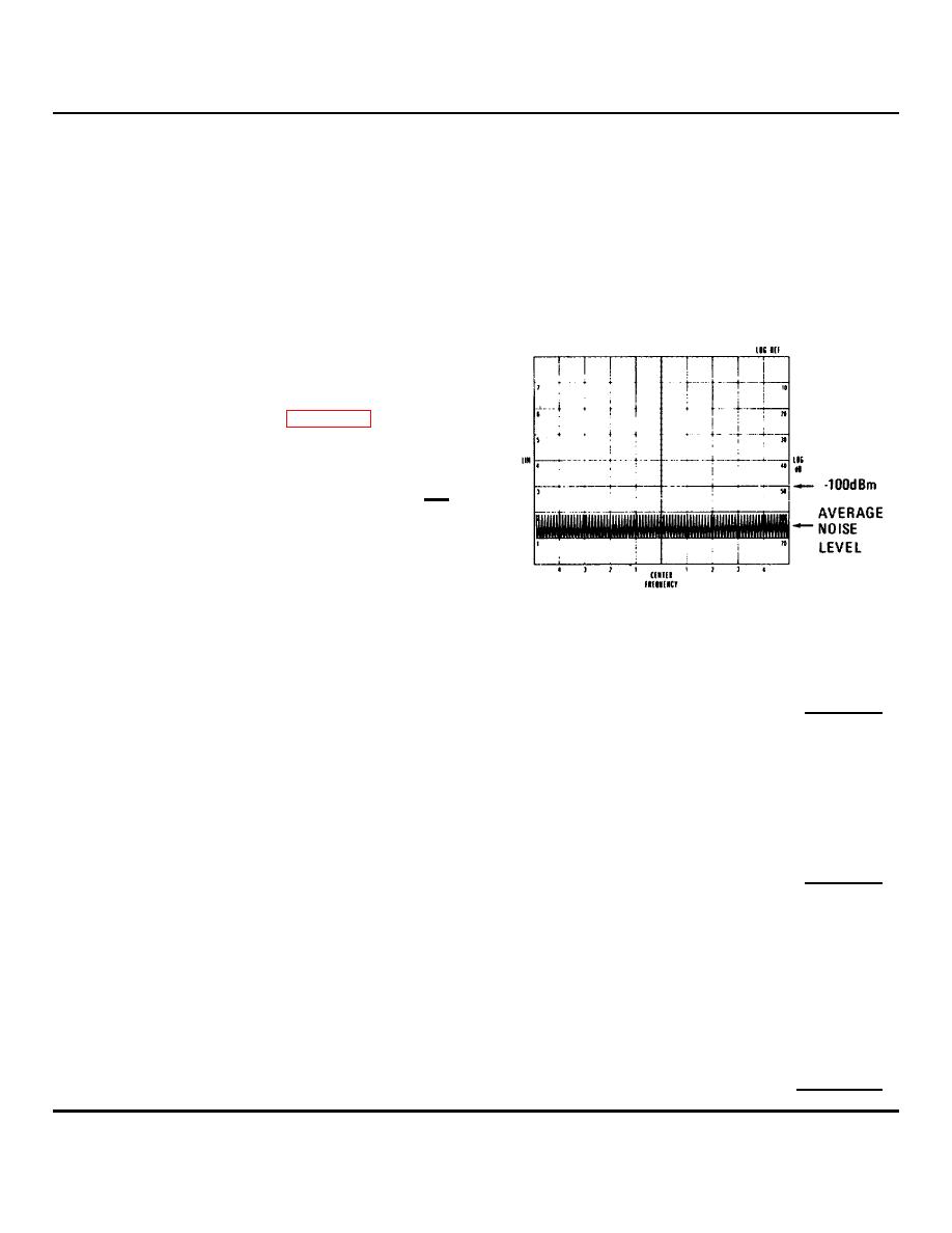
3. Observe the display as the analyzer scans from
10 to 110 MHz. The average noise level should
be less than -100 dBm, and no, residual
responses should occur. Figure 7-3 represents
a scan with no residual responses, and with the
average noise level indicated.
Residual Responses 10 - 110 MHz:
<-100 dBm
4. To check the analyzer from 1 MHz to 10 MHz,
make the following control settings:
FREQUENCY ............................................. 5 MHz
SCAN WIDTH PER DIVISION .................... 1 MHz
SCAN TIME PER DIVISION ............ 2 SECONDS
Figure 7-3. Residual Response Test:
10 to 110 MHz CRT-Display.
5. Observe the display for residual responses:
Residual Responses 1 - 10 MHz:
<-100 dBm
6. To check the analyzer from 200 kHz to 1 MHz, make the following control settings:
FREQUENCY .............................................................. Local Oscillator signal appears at left hand edge of gratic ule
SCAN WIDTH PER DIVISION ..................................................................................................................... 0 1 MHz
BANDWIDTH ................................................................................................................................................... 1 kHz
SCAN TIME PER DIVISION................................................................................................................. 5 SECONDS
7. Observe the display for residual responses over the last 8 horizontal div isions:
Residual Responses 200 kHz - 1 MHz:
<-100 dBm
8. To check the analyzer from 20 to 200 kHz, make the following control settings:
RANGE-MHz ..................................................................................................................................................... 0-11
FREQUENCY ....................................................................... Local Oscillator signal appears at left hand of graticule
SCAN WIDTH PER DIVISION ....................................................................................................................... 20 kHz
BANDWIDTH ................................................................................................................................................ 0 1 kHz
SCAN TIME PER DIVISION................................................................................................................. 5 SECONDS
LOG REF LEVEL......................................................................................................................................... -40 dBm
9. Observe the display for residual responses over the last nine horizontal div isions:
Residual Responses 20 - 200 kHz:
<-85 dBm
7-5


