
TM 11-6625-2781-14&P-2
Section VIII
Table 8-4. System Test and Troubleshooting Procedure (cont' )
d
TEST
FAULT
PROCEDURE
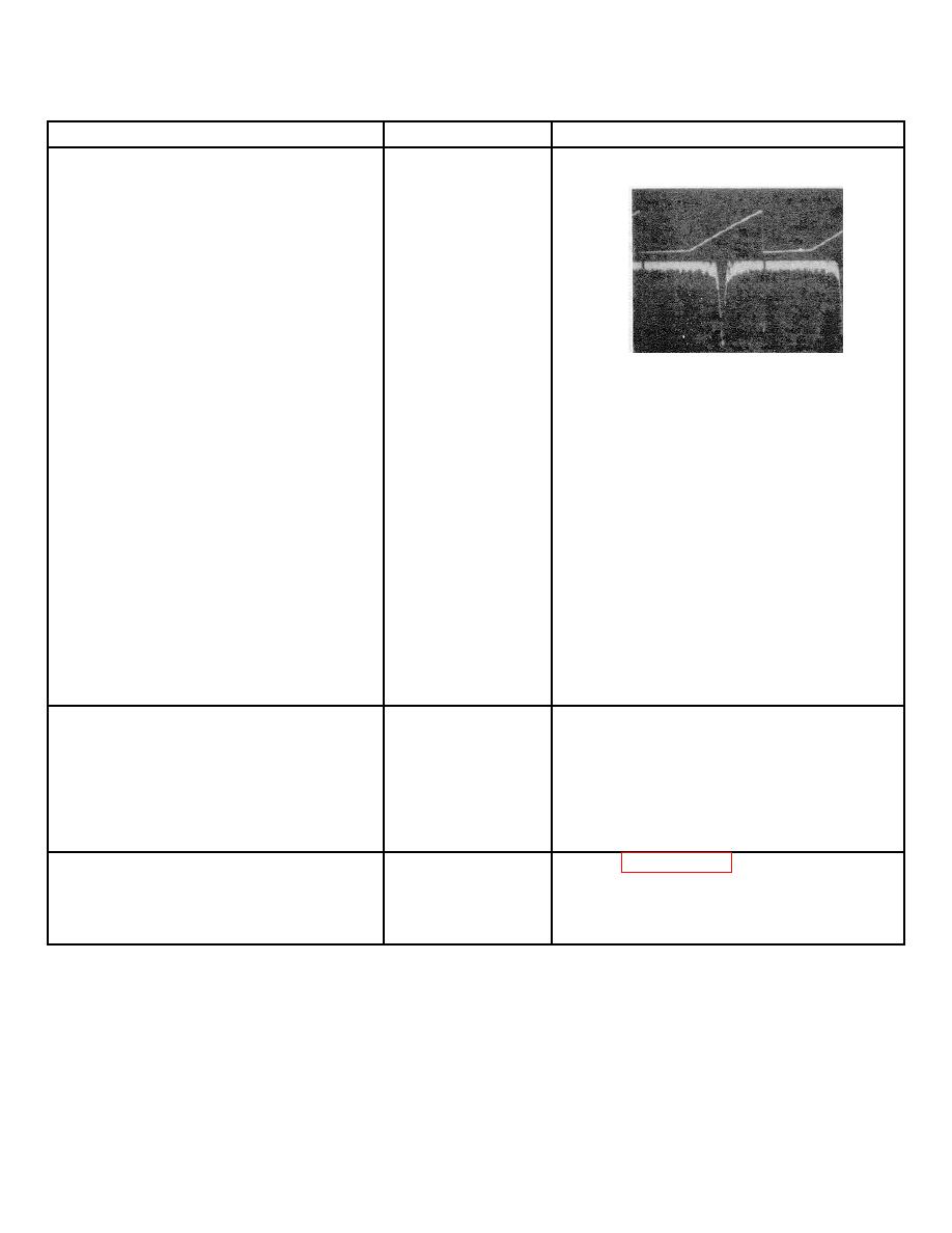
8. Set analyzer controls as follows:
FREQUENCY ...................... 40 MHz
FINE TUNE ....................... centered
BANDWIDTH ..................... 300 kHz
SCAN WIDTH ................ 0-100 MHz
SCAN WIDTH
PER DIVISION .................... 10 MHz
INPUT ATTENUATION.......... 10 dB
RANGE-MHz .......................... 0-110
TUNING STABILIZER ............... ON
BASE LINE CLIPPER................ ccw
SCAN TIME
PER DIVISION ........................ 2 ms
LOG REF LEVEL................ 10 dBm
LOG REF LEVEL Vernier . ........ccw
LOG/LINEAR ........................... LOG
VIDEO FILTER ........................ OFF
Sweep does not
See System Test and Troubleshooting
SCAN MODE............................. INT
extend to full
Procedure in 8552 Operating and Ser-
SCAN TRIGGER .................. .AUTO
width of
vice Manual. Check Scan Generator
graticule
and Deflection Amplifier assy's.
Connect CAL OUTPUT to RF
Not all signals
Same as above. Also refer to Service
INPUT using a BNC to BNC
present or im-
Sheet 8. First LO summing and
cable. The display should be
properly spaced.
shaping amplifier may be defective.
similar to that shown in the
procedure column.
Vary VERTICAL POSITION to
center baseline trace on bottom
Baseline trace
See System Test and Troubleshooting
CRT graticule. Signal amplitude
does not vary.
Procedure in 8552 Operating and Ser-
is unimportant in this test.
vice Manual. Check vertical deflection
Proceed to test 9.
circuit.
9. Set LOG REF LEVEL maximum
Focus and astig-
Refer to Display Section Manual and
ccw. Set SCAN TIME PER DI-
matism inopera-
repair as required.
VISION to 10 seconds and adjust
tive or trace will
focus and astigmatism. Adjust
not align.
trace align to center trace on
bottom CRT graticule. Proceed
to test 10.
10. Turn FREQUENCY control and
Marker is missing.
Refer to Service Sheet 8 and repair
observe the marker. Marker
the marker generator.
should move as FREQUENCY is
tuned. Proceed to test 11.
8-17
