
TM 11-6625-2781-14&P-2
Section VIII
Table 8-4. System Test and Troubleshooting Procedure (cont' )
d
TEST
FAULT
PROCEDURE
11.
Tune FREQUENCY control to
30 MHz signal
Check calibration and alignment of the
move the marker exactly under the
does not appear
analyzer.
signal three divisions from the left.
on CRT.
The signal will null when the marker
is tuned to the exact frequency of
the signal. Set SCAN WIDTH PER
DIVISION control to 0.05 MHz,
BANDWIDTH to 10 kHz, and
SCAN WIDTH to PER DIVISION.
30 MHz signal should appear close
to the center graticule on the CRT.
If correct signal is observed, proceed
-
to test 12.
12.
Adjust FREQUENCY to center
Signal is unstable -
Refer to Service Sheets 6 and 7, and
the 30 MHz signal on CRT, then
.
repair APC or reference signal circuits.
reduce SCAN WIDTH PER DI-
VISION to 10 kHz and re-center
FINE TUNE
See System Test and Troubleshooting
the display with FINE TUNE
does not vary
Procedure in 8552 Operating and Service
control. Signal centers properly.
signal position.
Manual.
Proceed to test 13.
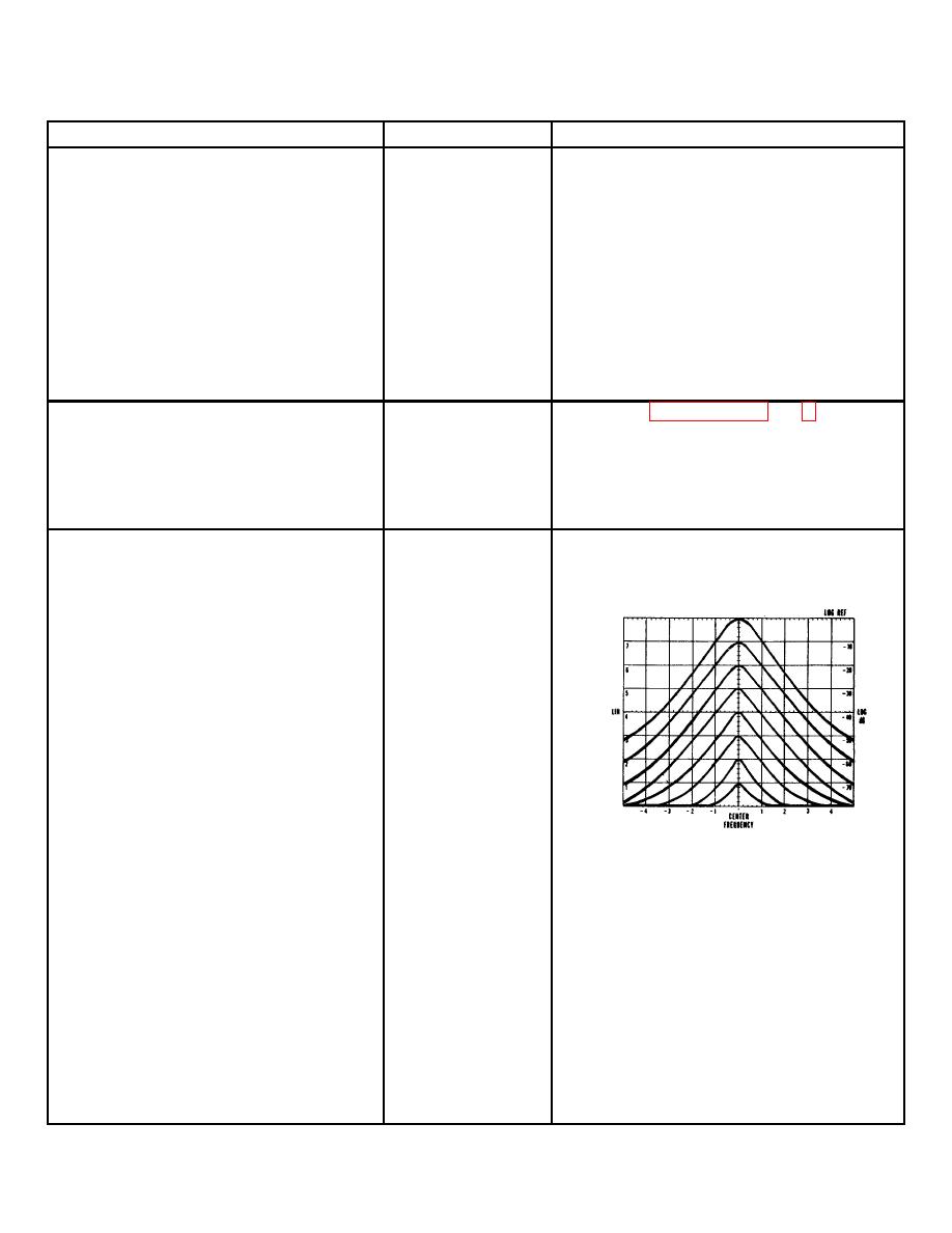
13.
Turn LOG REF LEVEL control
Each of the
See System Test and Troubleshooting
fully ccw. Top of signal should be
first 4 steps:
Procedure in 8552 Operating and Service
at the -70 dB graticule. Rotate
no increase
Manual.
LOG REF LEVEL seven steps cw.
in gain, not
CRT display should be as shown
10 dB gain,
in the figure. The fault column
or loss of
lists these steps in numerical order
signal.
beginning with the first step from
the ccw position.
Set INPUT ATTENUATION to
-30 dB and rotate LOG REF
LEVEL cw for remaining two
steps. Signal amplitude should
again reach the top CRT
graticule.
Steps 5 & 6
same as above
Check 3 MHz step gain amplifier
Step 7 same
as above
Check 3 MHz step gain amplifier
Step 8 & 9
same as above
Check 3 MHz step gain amplifier
All or most
levels incorrect
and cannot be
corrected by
INPUT ATTENUATION to -10
adjustment.
Check LIN/LOG amplifier
dB, LOG REF LEVEL to 0 dB.
No change in
Rotate LOG REF Vernier to full
signal level or
cw. Signal shown should increase
change is
by 12 dB. Proceed to test 14.
incorrect.
Check
variable
gain
amplifier
8-18
