
CAUTION
11. Check line Triggering
Use special care to avoid shorting the transformer
terminal to ground or other transformer terminal.
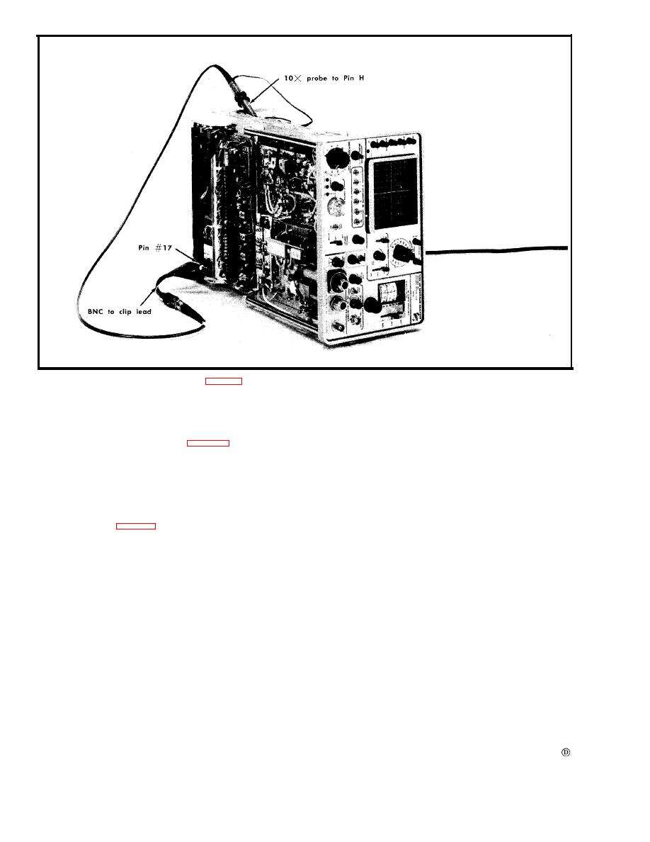
a. Equipment setup is shown in Fig. 6-13.
d. Set the TIME/DIV selector to 10 ms and turn the POWER
switch to the ON position.
b. Switch the Triggering SOURCE selector to LINE posi-
e. Check line triggering with the SLOPE switch in both
tion.
the + and - positions. Display must trigger on the cor-
rect slope.
c. Turn the POWER switch OFF, then connect a 10 t e s t
f. Remove the 10 probe and clip lead adapter. Return
probe and a BNC to clip lead adapter between pin H of
the TIME/DIV switch to 2 ms position and the Triggering
the Vertical Amplifier circuit board and pin 17 of the power
SOURCE switch to INT position.
transformer. See Fig. 6-13.
