
Section V
TM 11-6625-2781-14&P-2
ADJUSTMENT PROCEDURES (cont' )
d
5-25. 150 MHz Oscillator Adjustment
REFERENCE: Service Sheet 9.
DESCRIPTION: The 150 MHz oscillator is adjusted with a nonmetallic screwdriver to 150 MHz 10 kHz. the specified
operating frequency, output amplitude of the oscillator should be 150 to 230 millivolts rm During the adjustment caution
must be used to avoid damaging the tuning slug.
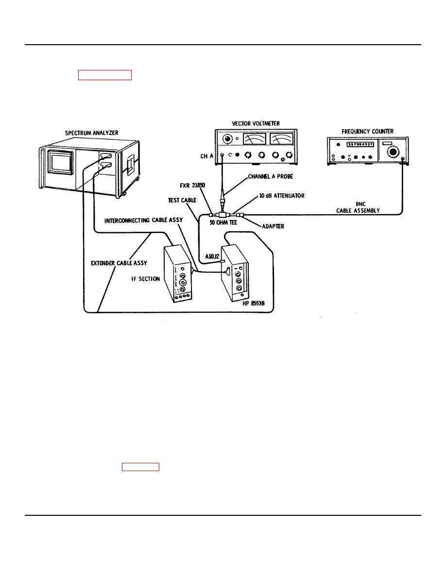
Figure 5-6. 150 MHz Oscillator Adjustment Test Setup
EQUIPMENT:
Vector Voltmeter ................................ ................................ ................................ ................................ ....... HP 8405A
Frequency Counter ................................ ................................ ................................ ......................... HP 5245L/5252A
Extender Cable Assembly ................................ ................................ ................................ ............... HP 11592-60015
Interconnecting Cable Assembly ................................ ................................ ................................ ..... HP 11592-60016
Cable Assembly ................................ ................................ ................................ .............................. HP 11592-60001
BNC Cable Assembly................................ ................................ ................................ .............................. HP 10503A
50-Ohm Tee ................................ ................................ ................................ ................................ ........... HP 11536A
Adapter, Male Type N to BNC Female ................................ ................................ ................................ .... UG-201A/U
10 dB Attenuator Pad................................ ................................ ................................ ................................ HP 8491A
Nonmetallic Tuning Tool
Type N Female to BNC Female Adapter ................................ ................................ ................................ ..FXR 21850
1. Connect test setup in Figure 5-6. Make the following control settings.
ANALYZER:
RANGE MHz ................................ ................................ ................................ ................................ ................... 0-110
FREQUENCY ................................ ................................ ................................ ................................ ................. 0 MHz
5-12
