Section V
TM 11-6625-2781-14&P-2
ADJUSTMENT PROCEDURES (cont' )
d
5-26. 120 MHz Low Pass Filter Check and Adjustment (cont'd)
ANALYZER Control Settings (cont'd)
LOG REF LEVEL ................................ ................................ ................................ ................................ ........ +10 dBm
VIDEO FILTER ................................ ................................ ................................ ................................ .............. 10 kHz
SCAN MODE ................................ ................................ ................................ ................................ ....................... INT
SCAN TRIGGER ................................ ................................ ................................ ................................ ............ AUTO
SCAN TIME PER DIVISION ................................ ................................ ................................ ........ 5 MILLISECONDS
2. Set the Tracking Generator/Counter controls as follows:
8443A:
OUTPUT LEVEL dBm................................ ................................ ................................ ................................ ............. 0
MODE................................ ................................ ................................ ................................ ............................ Marker
RESOLUTION ................................ ................................ ................................ ................................ ............... 100 Hz
3. Peak the response on the analyzer CRT using
FINE TUNE. Maximum amplitude should be
within 2 divisions of full scale.
4. Change INPUT ATTENUATION to 30 dB.
Switch the LOG/LINEAR control to LINEAR.
Adjust LINEAR SENSITIVITY so that trace is
centered on the 6-LIN line (left side of graticule).
divisions.
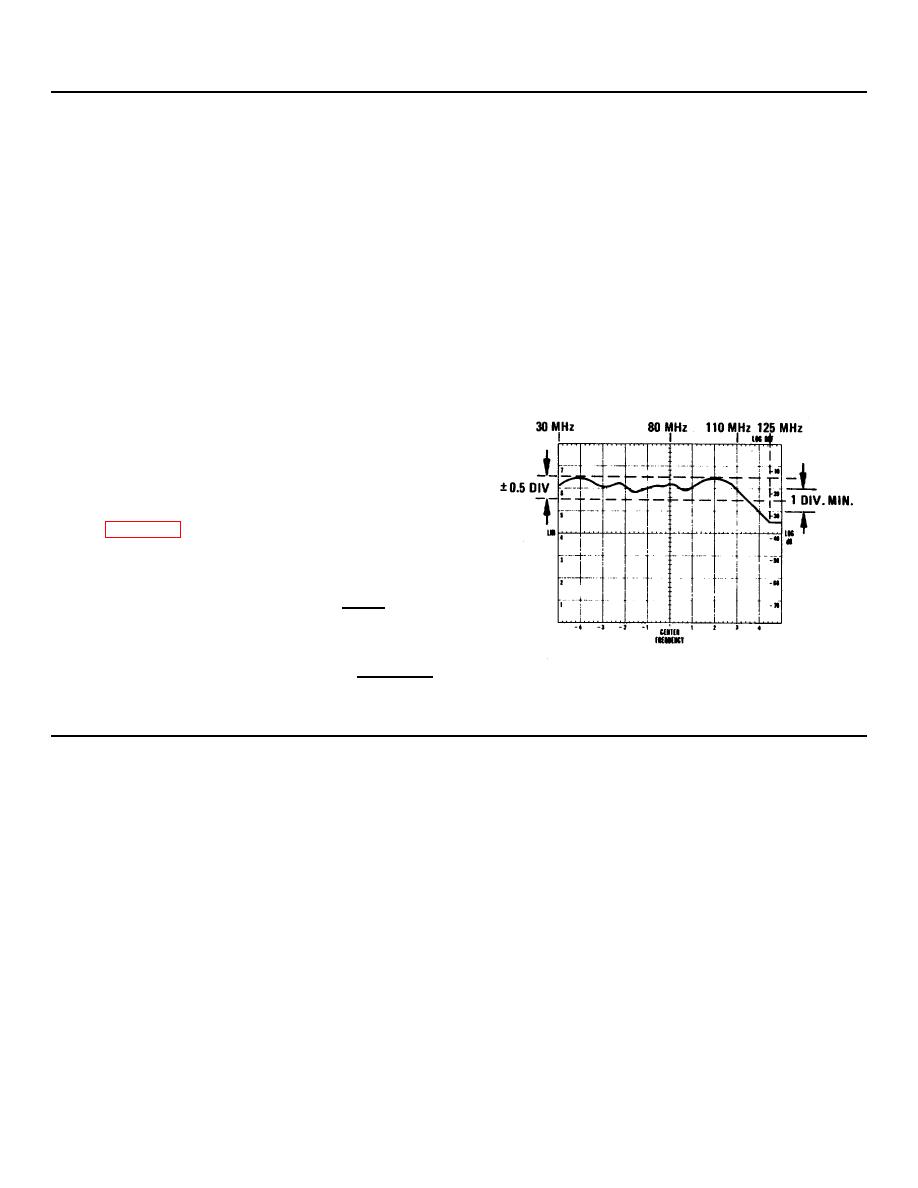
120 MHz LPF Flatness, 30-100 MHz:
5.5 _____6.5 Div
120 MHz LPF Roll-off between 110 MHz and
125 MHz:
1 Div _________
Figure 5-8. 120 MHz Bandpass Shape
5. If the filter is not within the limits in step 4,
adjust A11L1, 2, 3, and 4.
5-15


