
Section V
TM 11-6625-2781-14&P-2
ADJUSTMENT PROCEDURES (cont' )
d
5-26. 120 MHz Low Pass Filter Check and Adjustment
REFERENCE: Service Sheet 3.
DESCRIPTION: 120 MHz low-pass filter pass band response may be checked using frequency response test 4-24. The
120 MHz low-pass filter is adjusted for flatness between 30 and 110 MHz using the HP 8443A Tracking
Generator/Counter as a leveled tracking source. By connecting the spectrum analyzer (P4) to the Tracking
Generator/Counter, the Tracking Generator frequency range is synchronized to the analyzer first local oscillator. (The
analyzer and the tracking generator track the same frequency range, allowing a swept view of the 120 MHz bandpass
shape.)
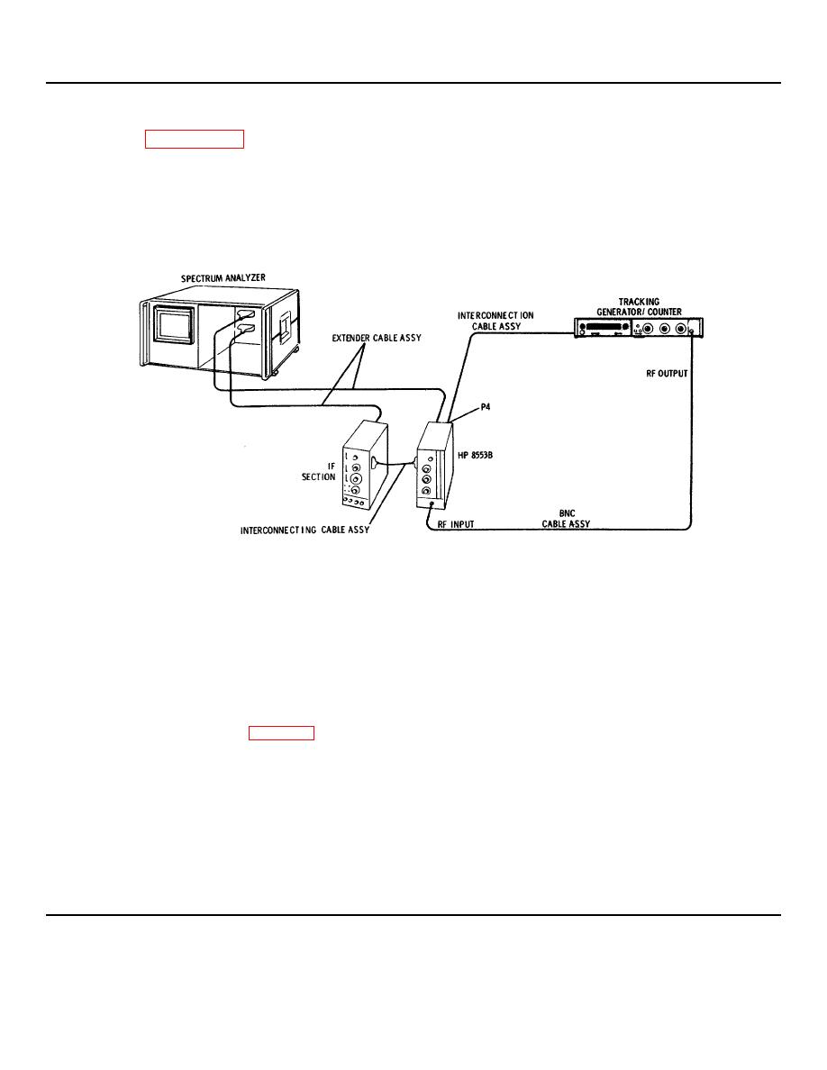
Figure 5-7. 120 MHz Low Pass Filter Adjustment Test Setup
EQUIPMENT:
Tracking Generator/Counter................................ ................................ ................................ ...................... HP 8443A
BNC Cable Assembly................................ ................................ ................................ .............................. HP 10503A
Extender Cable Assembly ................................ ................................ ................................ ............... HP 11592-60015
Nonmetallic Tuning Tool ................................ ................................ ................................ ..................... HP 8730-0013
Interconnecting Cable Assembly ................................ ................................ ................................ ..... HP 11592-60016
Cable Assembly ................................ ................................ ................................ .............................. HP 11592-60013
Interconnection Cable Assembly ................................ ................................ ................................ ..... HP 08443-60049
1. Connect the test setup in Figure 5-7 and make the following control settings:
ANALYZER:
RANGE MHz ................................ ................................ ................................ ................................ ................... 0-110
FREQUENCY ................................ ................................ ................................ ................................ ............... 80 MHz
FINE TUNE................................ ................................ ................................ ................................ ................ centered -
INPUT ATTENUATION................................ ................................ ................................ ................................ .... 10 dB
BANDWIDTH ................................ ................................ ................................ ................................ ............... 300 kHz
SCAN WIDTH ................................ ................................ ................................ ................................ ....PER DIVISION
SCAN WIDTH PER DIVISION ................................ ................................ ................................ ...................... 10 MHz
LOG/LINEAR ................................ ................................ ................................ ................................ ..................... LOG
5-14
