
TM 11-6625-2781-14&P-2
When this condition exists the output of the sampler is
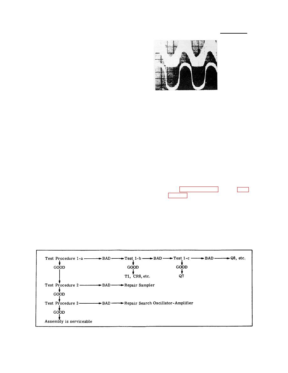
CONTROL SETTINGS:
random and the search oscillator-amplifier oscillates at
approximately 10 Hz.
The output of the search
Chan. A:
oscillator, amplifier, under these conditions, causes the
0.5V/Div
voltage control assembly to sweep the first local
Chan. B:
oscillator approximately 75 kHz.
0.05 V/Div
20 msec/Div
10:1 probes
As the first local oscillator is swept through one of the
MAGNIFIER X1
100 kHz calibration harmonics, the first local oscillator
output correlates to consecutive 100 kHz pulses from
Waveform GOOD and
the pulse generator in the sampler gate. Approximately
verification procedure
five 100 kHz pulses are required to accomplish phase
below also satisfactory,
lock. As the APC voltage from the sampler stabilizes,
assembly is functioning
the search oscillator amplifier stops oscillating and only
properly.
the APC signal is coupled to the voltage control
assembly as an error signal to maintain the phase
Waveform BAD:
Check Q1/Q2/Q3 and associated
locked condition.
components.
A second output is provided by the APC assembly
To verify proper operation of this circuit momentarily
through the TUNING STABILIZER switch and Reference
place the TUNING STABILIZER switch to OFF. The
Assembly A8 to control the third local oscillator in the IF
Channel B waveform should disappear while the switch
section. This signal acts as an offset voltage to shift the
is off. Next, reconnect the APC output lead to C1 and
47 MHz oscillator frequency to compensate for the
note that both waveforms disappear as the first local
frequency shift required to phase lock the first local
oscillator becomes phase locked.
oscillator. This compensation is required to maintain the
CRT display accuracy when switching from unstabilized
to stabilized operation.
NOTE:
When repairs are required to any
TEST PROCEDURE
portion of the APC assembly, it
should be adjusted in accordance
Connect the HP 180A/1801A/1821A Channel A input to
with Paragraphs 5-28 through 5-31 of
TP 3, the Channel B input to TP D, and observe the
waveform.
NOTE:
The
APC
output
must
be
disconnected from C1 to prevent the
first local oscillator from being phase
locked or these signals cannot be
observed.
Simplified Test Procedure Tree
8-34
