TM 11-6625-2781-14&P-2
voltage from the 47 MHz local oscillator summing
and provides a 6 volt peak-to-peak square wave output
amplifier.
at 100 kHz. This signal is applied to the APC assembly
(A6) where it is processed to provide phase lock and
frequency control signals.
TEST PROCEDURE
TEST PROCEDURE:
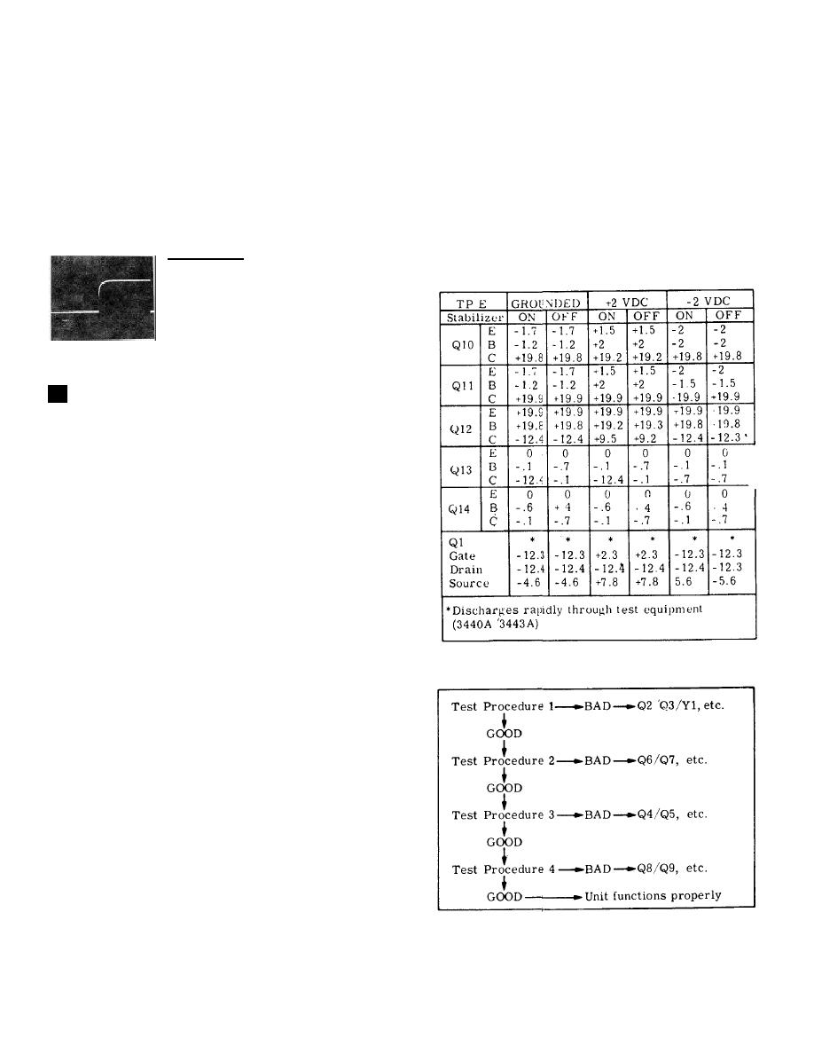
Normally the APC compensation circuit will require
service only if the IF section 47 MHz Oscillator is not
Connect the HP 180A/1801A/1821A to TP A (J1) and
operating properly. Using the HP 6215A Power Supply
observe the waveform.
to inject a simulated input as outlined in the chart below
and taking voltage measurements with the HP
CONTROL SETTINGS:
3440A/3443A should help to isolate the cause of
malfunction to a circuit or component.
1 /sec/Div
0.2 V/Div
10:1 probe
Waveform
GOOD:
Assembly
functions properly
Waveform BAD: Check Q8/Q9 and
associated components
APC COMPENSATION CIRCUIT
5
The input APC signal is grounded through the scan
width attenuator switch in scan widths of .05 MHz or
greater regardless of the position of the TUNING
STABILIZER switch. In scan widths of 20 kHz or less
the APC signal is grounded only when the TUNING
STABILIZER is in the OFF position.
When the SCAN WIDTH PER DIVISION switch is set to
20 kHz or less, the TUNING STABILIZER switch OFF
and the SCAN WIDTH set to PER DIVISION, a ground
is applied to the junction of R33 and R34 which
eliminates the +20 volts applied to the circuit through
R33 and allows C21 to discharge through R35.
Approximately 0.5 second after phase lock is initiated,
C21 discharges to a level which will allow Q14 to
conduct. When turned on, Q14 turns off Q13 and
causes relay K1 to deenergize. Relay K1 remains
Simplified Test Procedure Tree
deenergized as long as the analyzer is in a stabilized
mode.
During the 0.5 second time that relay K1 is energized
after initiation of the phase-lock cycle, the APC signal is
processed by operational amplifier Q10/Q11/Q12 and
applied to C23, which charges to the dc level of the
signal. When relay K1 opens, C23 cannot discharge
because of the high input impedance of Q1. The output
of Q1 is clamped at a level determined by the level of
the charge on C23 and is applied as an offset voltage to
the third local oscillator to compensate for frequency
shift required to phase lock the first local oscillator.
When the TUNING STABILIZER is turned OFF the
system is no longer phase locked. Relay K1 energizes,
allows C23 to discharge, which removes theoffset
8-36


