Section VIII
TM 11-6625-2781-14&P-2
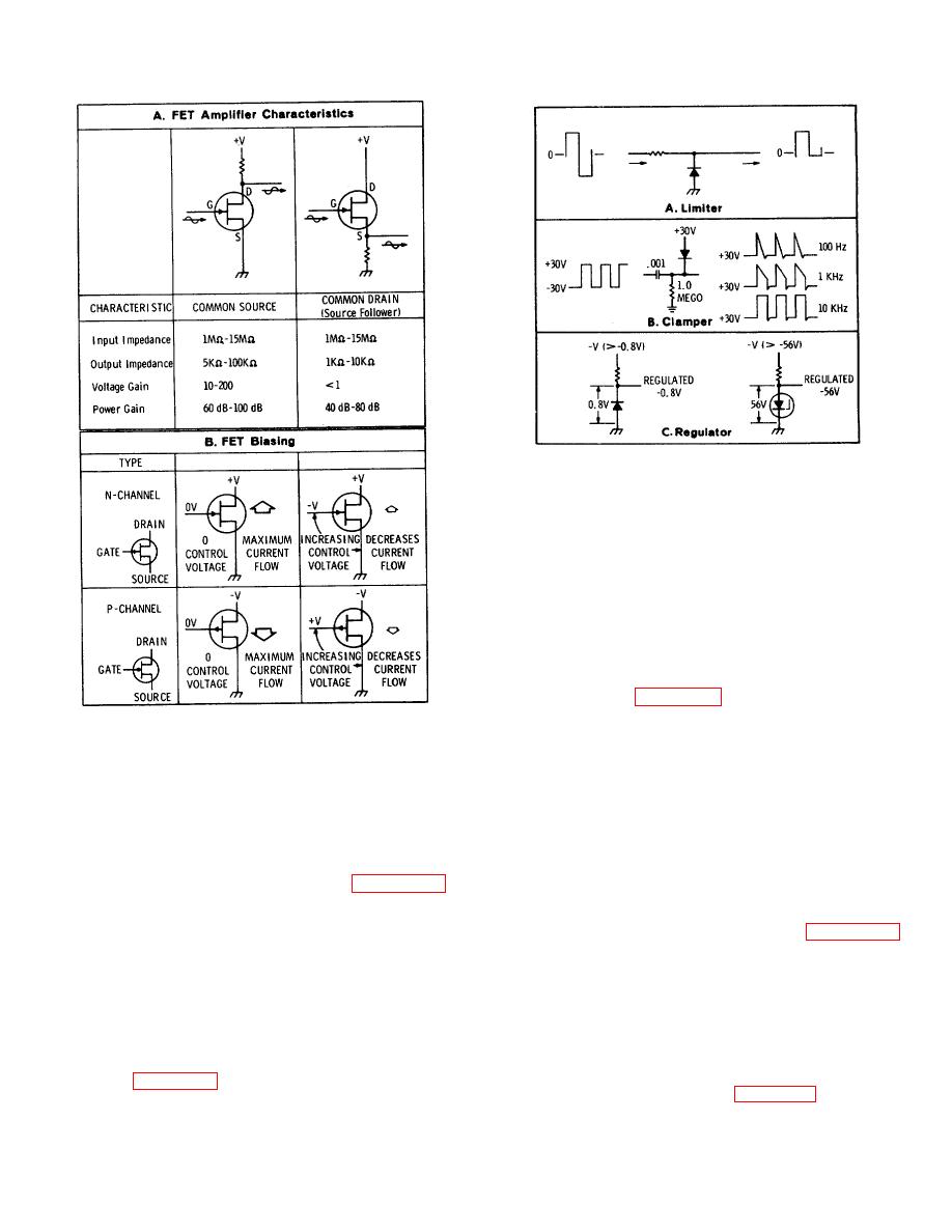
Figure 8-9. Basic Diode Circuits.
8-37. Diode Regulator. A diode regulator uses either
the
constant
reverse-bias
breakdown
voltage
characteristic of a breakdown diode or the constant
forward-bias voltage drop characteristic of a silicon
diode. Power supply reference voltages are generally
prov ided by breakdown diodes which maintain a
constant voltage when supplied with a reverse-bias
voltage greater than their specified breakdown voltage.
Regulated voltages can also be prov ided by a forward-
biased silicon diode which maintains a constant 0.6 to
0.8 volt drop.
connections for both types of diodes.
Figure 8-8. Field Effect Transistor Operation.
8-38. SPECIAL TYPES OF SEMICONDUCTORS
8-34. STANDARD DIODE CIRCUITS
8-39. Silicon Controlled Rectifier . An SCR is the
semiconductor equivalent of a gas thyratron. A voltage
8-35. Diode Limiter or Clipper . The limiter or clipper
applied to a control element switches the controlled
is a circuit which removes positive or negative peaks
rectifier to a conducting state when a positive voltage is
from a waveform. It can be used either as a waveform
simultaneously applied to the anode. The controlled
shaping circuit or as a protective device to prevent
rectifier continues conducting until the anode voltage is
damage from excessive voltages. Figure 8-9,
reduced to zero. Once triggered, the control element
Schematic A, shows a limiter which prevents the
has no control of the rectifier until it is turned off by
negative peak of the pulse from exceeding about X.6
removal of the voltage at the anode. Figure 8-10
volt. Note that for a conducting silicon diode the
illustrates the function of an SCR when used as a
cathode voltage is about 0.6 to 0.8 volt more negative
"crowbar" in a voltage regulation circuit.
than the anode.
8-36. Diode Clamp. The clamper is a circuit which
becomes a short circuit, rather than an open circuit, the
establishes either the positive or negative peak of a
waveform at a particular dc reference voltage; in other
output. Under these conditions the regulator circuits are
words, it prov ides a definite baseline voltage for the
no longer operative, and the load current is limited
waveform. Figure 8-9, Schematic B, shows a clamper
mainly by the load resistance. In Figure 8-10 the circuit
which prov ides a baseline of about +20 volts for a
negative pulse.
8-8


