
Section VIII
TM 11-6625-2781-14&P-2
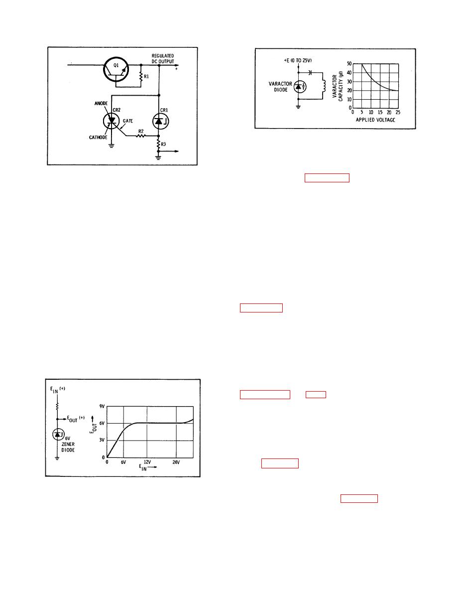
Figure 8-12. Varactor Characteristics.
ratings. When used in a voltage reference application,
a Zener diode is connected in the backward or minimum
current direction. Figure 8-11 shows a Zener diode
Figure 8-10. Silicon Controlled Rectifier
circuit and the resultant input and output voltage curve.
used as a Crowbar.
8-42. When used in a voltage reference application the
consisting of CR1, R2, and R3 controls the SCR control
Zener current is adjusted so that it is operating on the
element (gate). Since the SCR CR2 is directly across
flat portion of the curve.
The Zener diode then
the regulated output, it is always forward biased.
resembles a constant-voltage element such as a battery,
However, CR2 cannot conduct until the gate control
exhibiting only slight changes in voltage for a change in
level triggers it into conduction. When the regulator
current.
output voltage increases, the voltage drop across R3
increases. This increase is coupled to the SCR gate
8-43.
Varactor Diode.
Ordinary diodes when
through R2. When the SCR gate voltage reaches a
connected in the back direction exhibit a change in
predetermined level, the SCR conducts and shorts the
capacitance with a change in applied voltage. The
output of the regulator to ground. Once triggered into
varactor diode is specially designed to produce this
conduction, the SCR continues conducting until the
effect and exhibits relatively large changes in capacity.
positive voltage at the anode is completely removed. In
this manner external circuits are protected from damage
circuit connected in the back direction with respect to
due to excessive current flow when the series regulator
the applied dc voltage.
The curve indicates the
shorts out and voltage rises.
approximate two-to-one capacitance range for voltage
variations from 0 to 25 volts.
8-41. Zener Diode. Several types of Zener diodes are
used in circuits of the Spectrum Analyzer, mostly in
8-44. REPAIR
voltage reference applications. These diodes are quite
similar, the main differences being current and voltage
8-45. Part Location Aids. The locations of chassis-
mounted parts and major assemblies are shown in
components mounted on printed circuit boards or other
assemblies are shown on the appropriate schematic
diagram page or on the page opposite it. The part
reference designator is the assembly designator plus
the part designator. (Example: A100R9 is R9 on the
second converter A10).
For specific component
description and ordering information refer to the parts
list in Section VI.
8-46.
Factory Selected Components.
Some
component values are selected at the time of final
Figure 8-11. Zener Diode Characteristics.
checkout at the factory (see Table 5-2). Usually these
values are not extremely critical; they are selected to
prov ide optimum compatibility with associated
components. These components are identified on
8-9
